


Russian Federation
Russian Federation
The operation of the lifting equipment of a fishing vessel has a number of differences from similar shore devices or cranes and winches operated on transport vessels. The difference from coastal equipment is the external impact from the marine environment, manifested by on-board or keel rolling. The lifting equipment of a transport vessel, influenced by hydrometeorological factors, transports cargo with constant parameters, i.e. the effective load can be calculated according to a proven methodology in accordance with standards. The relevance of the task of improving the methodology for calculating operational loads acting on the lifting equipment of a fishing vessel is confirmed. The accuracy of mathematical models plays a key role in the development of an automatic control system, which must be taken into account when designing modern fishing vessels. When developing mathematical models, both hydrometeorological factors (wind and wave load, surface and underwater current) and variable parameters of the towed object (mass, hydrodynamic resistance, shape, movement on the ground, etc.) should be considered. Forecasting the dynamic behavior of each element of the “ship - winch - cable - towed object” system it will ensure operational and environmental safety, reliability, as well as energy and economic efficiency of the new fishing vessel as a whole. The method of coordinate separation used for mathematical modeling of the ship's winch drive, the operation of which is characterized by non-stationary dynamic processes arising from the effects of hydrometeorological factors and variable loading from the towed object, is presented. The advantage of this modeling method is the choice of any coordinate as an independent one, without being tied to the actual location.
winch, towed object, dynamic loads, coordinate separation, mathematical model
Introduction
The fishing fleet operating in the Azov-Black Sea basin requires global updating. The average age of vessels is more than 25 years. Under the circumstances, the issue of import substitution of ship equipment is becoming topical. The ship winch drive, as a ship auxiliary mechanism, has an impact on the reliability, safety and energy efficiency of the power plant and the ship as a whole. It is therefore particularly important to take into account the dynamic loads on the vessel winch on the side of the towed and lifted object. In particular, such non-stationary dynamic loads can be seen in the trawl winch of a fishing vessel. During trawl fishing, both hydrometeorological factors and variable loads may affect the winch. This can lead to stopping, failure of the drive of the lifting machine, overloading of the main and auxiliary engines, loss of stability of the vessel [1-3]. Therefore, when creating an automated control system for a trawl complex that directly affects the energy efficiency of the ship, it is necessary to predict the behavior of the elements of the winch drive. Existing mathematical models describing the dynamics of ship winches do not take into account non-stationary processes and variable loading of the towed object, which is necessary in the automation of the process [4-7]. Hence, the search for adequate models is an urgent task caused by the demands of practice.
Research materials and methods
The aim of the work is to build a mathematical model of movement of the system “ship - winch - rope - towed object” (Fig. 1).
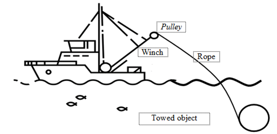
Fig. 1. System “ship - winch - rope - towed object”
The trawl winch consists of three solid bodies (Fig. 2). The solid body 1 is a rolling drum, which is a link with a hinge-fixed support, the solid body 2 - a rope from the drum to the pulley, which is also considered to be a fixed link, the solid body 4 - a towable object (TO) moving on the ground, the center of which is at point B. The movement of the solid body 4 is transmitted by the tension of the cable 3. By rotating the drum 1 with a given angular speed, the TO 4 will make a straight-line movement. Pulley movement in this case will not be taken into account.
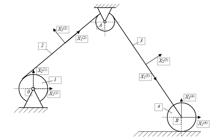
Fig. 2. Structural diagram of a trawl winch
In order to study the movement of this mechanism in the Cartesian coordinates, we will select a coordinate system for each solid body [8-11]. The centers of these local coordinate systems are assumed to be rigidly connected to the geometric center of the corresponding solid bodies.
Therefore, we define the Cartesian coordinates of the bodies (links) as follows in accordance with the Shaban method:
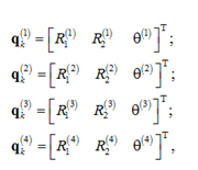
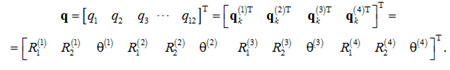
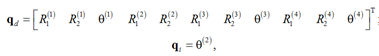
where ![]() are coordinates of the origin of the coordinate system X1(i)X2(i) of the i-th solid body, defined relative to the base coordinate system; θ(i) – angular orientation of the i-th solid body. Thus, the system vector q in Cartesian coordinates is defined as
are coordinates of the origin of the coordinate system X1(i)X2(i) of the i-th solid body, defined relative to the base coordinate system; θ(i) – angular orientation of the i-th solid body. Thus, the system vector q in Cartesian coordinates is defined as
However, these coordinates are not independent because of kinematic limitations on the movement of the mechanism elements. These limitations can be defined as follows. The solid body 1 is a fixed link, i.e.
R1(1) = 0; R2(1) = 0; θ(1) = 0.
These restrictions are basic. The position of the geometric center of the rope element 2 is relative to the center of the drum 1 - the point O in the system X1(1) X2(1) can be defined as
R(2) + A(2) = ū0(2),
where R(2) = [R1(2) R2(2)]T; A(2) – a matrix of transformation from the local coordinate system of the solid body 2 to the base coordinate system; ū0(2) – a vector of the position of the point O in the coordinate system of the rope 2, i.e.

where l(2) – a rope length 2.
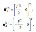
The cable element 2 is connected to the cable element 3 through the pulley A. Denoting the length of the cable element 3 through l(3), we will write down the position of the cable elements 2 and 3 in the Cartesian coordinates as
R(2) + A(2)ūA(2) – R(3) – A(3)ūA(3) = 0,
where R(i) = [R1(i) R2(i)]T; A(i) – a matrix of transformation from the local coordinate system of the solid body i to the base coordinate system; ūA(i)(i = 2.3) – the local position of the body in the connection, in this case they have the form
The connection of bodies 3 (a section of a cable of variable length) and 4 (a towable object) is assumed to be hinged at a point B. Therefore, let’s write the connection between these bodies as
R(3) + A(3)ūB(3) – R(4) – A(4)ūB(4) = 0,
in which

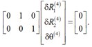
Movement of the towed object 4 should meet the following kinematic restriction
R2(4) = 0; θ(4) = 0.
The results of the research and discussion
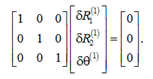
The mechanical system that is being discussed, which is known as a “winch - rope - towed object”, includes 12 Cartesian coordinates and 11 algebraic equations. These equations can be rephrased as follows: 3 basic restrictions, 2 restrictions that fix the coordinates of the O point, 4 restrictions that describe the mobile connections at points A and B and 2 restrictions describing the movement of the towed object [12-14]. That is, the studied system has one degree of freedom. Then, taking a virtual change of generalized coordinates of the system, the basic limitations
δR1(1) = 0; δR2(1) = 0; δθ(1) = 0.
Write down in a matrix form
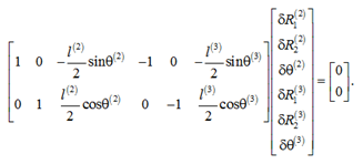
Restrictions on the base position of the point O are
δR(2) + Aθ(2)ū0(2) – δθ(2) = 0,
where Aθ(2) – partial derivative of the flat conversion A(2) on θ(2). Using the definition ū0(2), write down the above equation as
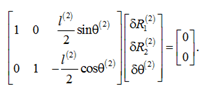
Rotation of the drum relative to the center A is obtained in the form of
or
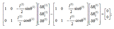
For rotational connection at the point B we have
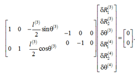
Restriction of movement of towed object at the point B is provided by the expression
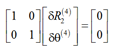
or
By combining both equations, we will have
Cqδq = 0,
where
![]()
and Cq – Jacobi matrix of dimension 11×12, which can be written as
Cq = [Ci,j],
where non-zero elements are defined as
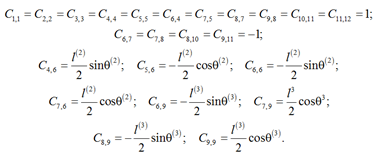
If θ(2) is chosen as an independent coordinate, then the Jacobi matrix will take the form of
Cqdδqd + Cqiδqi = 0,
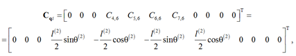
where Cqd – Jacobi matrix connected to the dependent coordinates. It’s a square matrix, measuring 11×11; Cqi – Jacobi matrix connected to the independent coordinate θ(2). In this case Cqi is an 11-dimensional Vector of dependent and independent coordinates defined as
the Vector Cqi is defined as
and the matrix Cqd is defined as
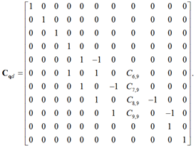
Obviously, Cqd is a degenerate matrix that can be inverted to write a vector δqd through a change in the δθ(2) system’s degree of freedom as
δqd = – Cqd–1 Cqi δθ(2).
The peculiarity of this simulation method is that any derivative - the angle of rotation, as in this case, or the movement of the towed object along a horizontal surface - can be chosen as independent R1(4), i.e. qi = R1(4),
![]()
This means that, using a coordinate partition, it is possible to record the change of a set of qd coordinates by changing another set of qi.
In the case that in a multi-channel system the identification of the matrix Cqd is difficult due to its non-degeneracy, numerical methods can be used.
Conclusion
The proposed method of generalized coordinate partitioning for mathematical modeling of the system “ship - winch - rope - towed object” can be recommended for formalization of this kind of lifting devices, as independent, you can choose any coordinate without being tied to the actual move. Implementation of the obtained mathematical models is planned to be carried out by means of Python language, using matplotlib, graphical interface DearPyGUI.
1. Karpenko V. P., Torban S. S. Mekhanizatsiia i avtomatizatsiia protsessov promyshlennogo rybolovstva: uchebnoe posobie [Mechanization and automation of industrial fishing processes: study guide]. Moscow, Agropromizdat, 1990. 464 p.
2. Te A. M. Ekspluatatsiia sudovykh vspomogatel'nykh mekhanizmov, sistem i ustroistv [Operation of ship auxiliary mechanisms, systems and devices]. Vladivostok, Izd-vo Morskogo gosudarstvennogo universiteta, 2014. 86 p.
3. Bashurov B. P., Skiba A. N., Chebanov V. S. Funktsional'naia nadezhnost' i kontrol' tekhnicheskogo sostoianiia su-dovykh vspomogatel'nykh mekhanizmov: uchebnoe posobie [Functional reliability and control of the technical condition of ship's auxiliary mechanisms: textbook]. Novorossiisk, Izd-vo MGA imeni admirala F. F. Ushakova, 2009. 192 p.
4. Pashentsev S. V. Upravlenie protsessom buksirovki tankera posredstvom regulirovaniia natiazheniia trosa [Control of the tanker towing process by adjusting the cable tension]. Vestnik Moskovskogo gosudarstvennogo tekhnicheskogo universiteta, 2018, vol. 21, no. 4, pp. 577-586.
5. Kozhanov V. S., Ustalkov S. O., Khudoshina A. O. Matematicheskie modeli buksirovochnykh trosov [Mathematical models of tow ropes]. Matematicheskie metody v tekhnologiiakh i tekhnike, 2022, no. 5, pp. 62-68.
6. Al'tshul' B. A., Ermakova T. V. Analiz matematicheskoi modeli prostranstvennogo dvizheniia dvukhvaernogo tralovogo kompleksa s peremennoi dlinoi vytravlennykh vaerov [Analysis of a mathematical model of spatial motion of a two-bay trawl complex with variable length of etched vaers]. Materialy VI Mezhdunarodnogo Baltiiskogo morskogo foruma (Kaliningrad, 03-06 sentiabria 2018 g.). Kaliningrad, Obosoblennoe strukturnoe podrazdelenie «Baltiiskaia gosudarstvennaia akademiia rybopromyslovogo flota» FGBOU VO «Kaliningradskii gosudarstvennyi tekhnicheskii universitet», 2018. Vol. 1. Pp. 144-149.
7. Nedostup A. A., Razhev A. O., Nasenkov P. V., Konovalova K. V., Bykov A. A. Proizvoditel'nost' sil tralovoi sistemy - IV: matematicheskoe modelirovanie (chast' II) [Performance of the trawl system forces - IV: mathematical modeling (Part II)]. Vestnik Astrakhanskogo gosudarstvennogo tekhnicheskogo universiteta. Seriia: Rybnoe khoziaistvo, 2022, no. 1, pp. 32-38.
8. Babakov I. M. Teoriia kolebanii [Oscillation theory]. Moscow, Nauka Publ., 1976. 592 p.
9. Anan'ev I. V. Spravochnik po raschetu sobstvennykh kolebanii uprugikh sistem [Handbook on the calculation of natural oscillations of elastic systems]. Moscow, Leningrad, OGIZ; Gostekhizdat, 1946. 223 p.
10. Biderman V. L. Teoriia mekhanicheskikh kolebanii [Theory of mechanical vibrations]. Moscow, Vysshaia shkola Publ., 1980. 408 p.
11. Timoshenko S. P. Kolebaniia v inzhenernom dele [Fluctuations in engineering]. Moscow, Mashinostroenie Publ., 1985. 472 p.
12. Ivanovskaia A. V. Printsipy modelirovaniia privoda sudovogo gruzopod"emnogo oborudovaniia [Principles of modeling the drive of marine lifting equipment]. Vestnik Kerchenskogo gosudarstvennogo morskogo tekhnologicheskogo universiteta, 2023, no. 1, pp. 65-72.
13. Ivanovskaia A. V., Zhukov V. A. Modelirovanie raschetnykh nagruzok, deistvuiushchikh so storony tralovoi sistemy na lebedku rybopromyslovogo sudna [Modeling of design loads acting from the trawl system on the winch of a fishing vessel]. Vestnik gosudarstvennogo universiteta morskogo i rechnogo flota imeni admirala S. O. Makarova, 2020, vol. 12, no. 5, pp. 935-944.
14. Ivanovskaya A., Zhukov V. Basic principles of mathematical modeling of operating modes of deck equipment for fishing vessels. Transportation Research Procedia, 2021, vol. 54, pp. 104-110. DOI:https://doi.org/10.1016/j.trpro.2021.02.053.
