


Россия
Россия
Работа грузоподъемного оборудования рыбопромыслового судна имеет ряд отличий от подобного рода береговых устройств или кранов и лебедок, эксплуатирующихся на транспортных судах. Отличием от берегово-го оборудования является внешнее воздействие от морской среды, проявляющееся бортовой или килевой качкой. Грузоподъемное оборудование транспортного судна, испытывая влияние гидрометеорологических факторов, осуществляет транспортировку груза с постоянными параметрами, т. е. действующую нагрузку можно рассчитать по апробированной методике в соответствии со стандартами. Подтверждается актуальность задачи совершенствования методики расчета эксплуатационных нагрузок, действующих на грузоподъемное оборудование рыбопромыслового судна. Точность математических моделей играет ключевую роль при разработке системы автоматического управления, что необходимо учитывать при проектировании современных рыбопромысловых судов. При разработке математических моделей следует предусматривать как гидрометеорологические факторы (ветровая и волновая нагрузка, поверхностное и подводное течение), так и переменные параметры буксируемого объекта (масса, гидродинамическое сопротивление, форма, движение по грунту и т. д.). Прогнозирование динамического поведения каждого элемента системы «судно – лебедка – трос – буксируемый объект» позволит обеспечить эксплуатационную и экологическую безопасность, надежность, а также энергетическую и экономическую эффективность нового рыбопромыслового судна в целом. Представлен метод координатного разделения, используемый для математического моделирования привода судовой лебедки, работа которой отличается нестационарными динамическими процессами, возникающими из-за воздействия гидрометеорологических факторов и переменного нагружения со стороны буксируемого объекта. Преимуществом такого метода моделирования является выбор в качестве независимой любой координаты, не привязываясь к действительному перемещению.
лебедка, буксируемый объект, динамические нагрузки, координатное разделение, математическая модель
Introduction
The fishing fleet operating in the Azov-Black Sea basin requires global updating. The average age of vessels is more than 25 years. Under the circumstances, the issue of import substitution of ship equipment is becoming topical. The ship winch drive, as a ship auxiliary mechanism, has an impact on the reliability, safety and energy efficiency of the power plant and the ship as a whole. It is therefore particularly important to take into account the dynamic loads on the vessel winch on the side of the towed and lifted object. In particular, such non-stationary dynamic loads can be seen in the trawl winch of a fishing vessel. During trawl fishing, both hydrometeorological factors and variable loads may affect the winch. This can lead to stopping, failure of the drive of the lifting machine, overloading of the main and auxiliary engines, loss of stability of the vessel [1-3]. Therefore, when creating an automated control system for a trawl complex that directly affects the energy efficiency of the ship, it is necessary to predict the behavior of the elements of the winch drive. Existing mathematical models describing the dynamics of ship winches do not take into account non-stationary processes and variable loading of the towed object, which is necessary in the automation of the process [4-7]. Hence, the search for adequate models is an urgent task caused by the demands of practice.
Research materials and methods
The aim of the work is to build a mathematical model of movement of the system “ship - winch - rope - towed object” (Fig. 1).
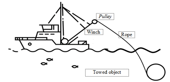
Fig. 1. System “ship - winch - rope - towed object”
The trawl winch consists of three solid bodies (Fig. 2). The solid body 1 is a rolling drum, which is a link with a hinge-fixed support, the solid body 2 - a rope from the drum to the pulley, which is also considered to be a fixed link, the solid body 4 - a towable object (TO) moving on the ground, the center of which is at point B. The movement of the solid body 4 is transmitted by the tension of the cable 3. By rotating the drum 1 with a given angular speed, the TO 4 will make a straight-line movement. Pulley movement in this case will not be taken into account.
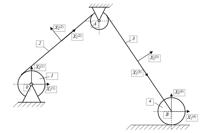
Fig. 2. Structural diagram of a trawl winch
In order to study the movement of this mechanism in the Cartesian coordinates, we will select a coordinate system for each solid body [8-11]. The centers of these local coordinate systems are assumed to be rigidly connected to the geometric center of the corresponding solid bodies.
Therefore, we define the Cartesian coordinates of the bodies (links) as follows in accordance with the Shaban method:
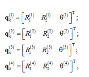
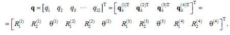
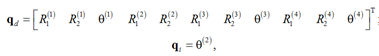
where ![]() are coordinates of the origin of the coordinate system X1(i)X2(i) of the i-th solid body, defined relative to the base coordinate system; θ(i) – angular orientation of the i-th solid body. Thus, the system vector q in Cartesian coordinates is defined as
are coordinates of the origin of the coordinate system X1(i)X2(i) of the i-th solid body, defined relative to the base coordinate system; θ(i) – angular orientation of the i-th solid body. Thus, the system vector q in Cartesian coordinates is defined as
However, these coordinates are not independent because of kinematic limitations on the movement of the mechanism elements. These limitations can be defined as follows. The solid body 1 is a fixed link, i.e.
R1(1) = 0; R2(1) = 0; θ(1) = 0.
These restrictions are basic. The position of the geometric center of the rope element 2 is relative to the center of the drum 1 - the point O in the system X1(1) X2(1) can be defined as
R(2) + A(2) = ū0(2),
where R(2) = [R1(2) R2(2)]T; A(2) – a matrix of transformation from the local coordinate system of the solid body 2 to the base coordinate system; ū0(2) – a vector of the position of the point O in the coordinate system of the rope 2, i.e.

where l(2) – a rope length 2.
The cable element 2 is connected to the cable element 3 through the pulley A. Denoting the length of the cable element 3 through l(3), we will write down the position of the cable elements 2 and 3 in the Cartesian coordinates as
R(2) + A(2)ūA(2) – R(3) – A(3)ūA(3) = 0,
where R(i) = [R1(i) R2(i)]T; A(i) – a matrix of transformation from the local coordinate system of the solid body i to the base coordinate system; ūA(i)(i = 2.3) – the local position of the body in the connection, in this case they have the form
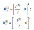
The connection of bodies 3 (a section of a cable of variable length) and 4 (a towable object) is assumed to be hinged at a point B. Therefore, let’s write the connection between these bodies as
R(3) + A(3)ūB(3) – R(4) – A(4)ūB(4) = 0,
in which

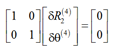
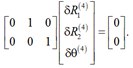
Movement of the towed object 4 should meet the following kinematic restriction
R2(4) = 0; θ(4) = 0.
The results of the research and discussion
The mechanical system that is being discussed, which is known as a “winch - rope - towed object”, includes 12 Cartesian coordinates and 11 algebraic equations. These equations can be rephrased as follows: 3 basic restrictions, 2 restrictions that fix the coordinates of the O point, 4 restrictions that describe the mobile connections at points A and B and 2 restrictions describing the movement of the towed object [12-14]. That is, the studied system has one degree of freedom. Then, taking a virtual change of generalized coordinates of the system, the basic limitations
δR1(1) = 0; δR2(1) = 0; δθ(1) = 0.
Write down in a matrix form
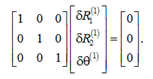
Restrictions on the base position of the point O are
δR(2) + Aθ(2)ū0(2) – δθ(2) = 0,
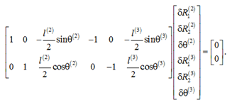
where Aθ(2) – partial derivative of the flat conversion A(2) on θ(2). Using the definition ū0(2), write down the above equation as
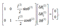
Rotation of the drum relative to the center A is obtained in the form of
or
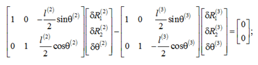
For rotational connection at the point B we have
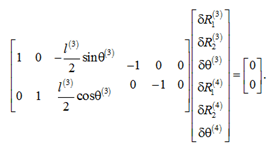
Restriction of movement of towed object at the point B is provided by the expression
or
By combining both equations, we will have
Cqδq = 0,
where
![]()
and Cq – Jacobi matrix of dimension 11×12, which can be written as
Cq = [Ci,j],
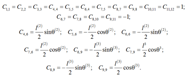
where non-zero elements are defined as
If θ(2) is chosen as an independent coordinate, then the Jacobi matrix will take the form of
Cqdδqd + Cqiδqi = 0,
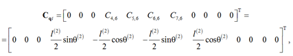
where Cqd – Jacobi matrix connected to the dependent coordinates. It’s a square matrix, measuring 11×11; Cqi – Jacobi matrix connected to the independent coordinate θ(2). In this case Cqi is an 11-dimensional Vector of dependent and independent coordinates defined as
the Vector Cqi is defined as
and the matrix Cqd is defined as
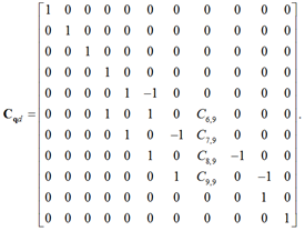
Obviously, Cqd is a degenerate matrix that can be inverted to write a vector δqd through a change in the δθ(2) system’s degree of freedom as
δqd = – Cqd–1 Cqi δθ(2).
The peculiarity of this simulation method is that any derivative - the angle of rotation, as in this case, or the movement of the towed object along a horizontal surface - can be chosen as independent R1(4), i.e. qi = R1(4),
![]()
This means that, using a coordinate partition, it is possible to record the change of a set of qd coordinates by changing another set of qi.
In the case that in a multi-channel system the identification of the matrix Cqd is difficult due to its non-degeneracy, numerical methods can be used.
Conclusion
The proposed method of generalized coordinate partitioning for mathematical modeling of the system “ship - winch - rope - towed object” can be recommended for formalization of this kind of lifting devices, as independent, you can choose any coordinate without being tied to the actual move. Implementation of the obtained mathematical models is planned to be carried out by means of Python language, using matplotlib, graphical interface DearPyGUI.
1. Карпенко В. П., Торбан С. С. Механизация и автоматизация процессов промышленного рыболовства: учеб. пособие. М.: Агропромиздат, 1990. 464 с.
2. Тё А. М. Эксплуатация судовых вспомогательных механизмов, систем и устройств. Владивосток: Изд-во Мор. гос. ун-та, 2014. 86 с.
3. Башуров Б. П., Скиба А. Н., Чебанов В. С. Функциональная надежность и контроль технического состояния судовых вспомогательных механизмов: учеб. пособие. Новороссийск: Изд-во МГА им. адм. Ф. Ф. Ушакова, 2009. 192 с.
4. Пашенцев С. В. Управление процессом буксировки танкера посредством регулирования натяжения троса // Вестн. Москов. гос. техн. ун-та. 2018. Т. 21. № 4. С. 577-586.
5. Кожанов В. С., Усталков С. О., Худошина А. О. Математические модели буксировочных тросов // Матем. мето-ды в технологиях и технике. 2022. № 5. С. 62-68.
6. Альтшуль Б. А., Ермакова Т. В. Анализ математической модели пространственного движения двухваерного тралового комплекса с переменной длиной вытравленных ваеров // Материалы VI Междунар. Балт. мор. форума (Ка-лининград, 03-06 сентября 2018 г.). Калининград: Обособл. структур. подразделение «Балтийская государственная академия рыбопромыслового флота» ФГБОУ ВО «Калининградский государственный технический университет», 2018. Т. 1. С. 144-149.
7. Недоступ А. А., Ражев А. О., Насенков П. В., Коновалова К. В., Быков А. А. Производительность сил траловой системы - IV: математическое моделирование (часть II) // Вестн. Астрахан. гос. техн. ун-та. Сер.: Рыбное хозяйство. 2022. № 1. С. 32-38.
8. Бабаков И. М. Теория колебаний. М.: Наука, 1976. 592 с.
9. Ананьев И. В. Справочник по расчету собственных колебаний упругих систем. М., Л.: ОГИЗ; Гостехиздат, 1946. 223 с.
10. Бидерман В. Л. Теория механических колебаний. М.: Высш. шк., 1980. 408 с.
11. Тимошенко С. П. Колебания в инженерном деле. М.: Машиностроение, 1985. 472 с.
12. Ивановская А. В. Принципы моделирования привода судового грузоподъемного оборудования // Вестн. Керч. гос. мор. технолог. ун-та. 2023. № 1. С. 65-72.
13. Ивановская А. В., Жуков В. А. Моделирование расчетных нагрузок, действующих со стороны траловой си-стемы на лебедку рыбопромыслового судна // Вестн. Гос. ун-та мор. и реч. флота им. адм. С. О. Макарова. 2020. Т. 12. № 5. С. 935-944.
14. Ivanovskaya A., Zhukov V. Basic principles of mathematical modeling of operating modes of deck equipment for fishing vessels // Transportation Research Procedia. 2021. V. 54. P. 104-110. DOI:https://doi.org/10.1016/j.trpro.2021.02.053.
