


Russian Federation
Transshipment cranes of the checkpoint of the Lenpodyemtransmash plant are widely used in river and sea ports, at industrial enterprises for grappling transshipment of bulk cargo and for working with piece loads or containers, as well as for transshipment of scrap metal and rolled metal using lifting electromagnets. It is proposed to eliminate the uncertainties caused by the incompatibility of one-dimensional (rod) and two-dimensional (plate) finite elements having a different number of degrees of freedom, 12 and 20, when developing digital twins of portal cranes of the Lenpodyemtransmash plant on the example of the CHECKPOINT 16/32t crane by approximating axisymmetric shells of the portal head with rod finite elements. The method is based on the equality of the potential shear energy of the finite element model of the plate and the potential energy of the approximating rod model, the elements of which work on tension/compression, which made it possible to move from the finite element model of the GEARBOX 16/32t reloading crane, built on the basic finite elements of Kirchhoff plates, to the finite element model of the crane based on the core base finite elements. A mathematical model of a matrix equation of static equilibrium with many degrees of freedom is proposed, the numerical solution of which by the Gauss method allows us to proceed to six-component internal forces in each finite element due to the corresponding vector of external loads reduced to the degrees of freedom of the calculated finite element model. The possibility of inter-pretation of bearing elements of spatial metal structures of portal cranes by both one-dimensional rod and two-dimensional plate finite elements is investigated, a re-evaluation of traditional views on the computational analysis of the stress-strain state of metal structures of portal cranes in the field of reliable determination of their bearing capacity during operation in ports, especially in the field of assessing post-repair risk analysis and the resource of reloading cranes is proposed, those who have completed the standard service life in the port and have undergone capital repairs. A calculated rod finite element idealized model of a PPC 16/32t gantry crane for transshipment of cargo in river and sea ports is constructed, demonstrating the transition from a real design to a calculation model based on geometric principles of discretization of both rod and continuum elements by the basic rod end elements of the crane, as a result of which the digital calculation model should be detailed and complex, like a system with many degrees of freedom. The algorithm of application of the digital calculation model of the crane is given on the example of static finite element calculation analysis of the KPP 16/32t crane.
portal crane, portal frame crane, calculation finite element model, rod finite element, digitizing geometric principle, a multiple degree of freedom, matrix equation of static balance
Introduction
Considerable experience has been accumulated in the application of finite element theory in the computational analysis of machine-building and other types of structures based, as a rule, on four types of basic finite elements - rod (one-dimensional), plate, two-dimensional, tetrahedral and hexahedral - as three-dimensional finite elements, the basics of theory and practice of which are presented in a number of authoritative publications, among which the leading positions are considered to be assigned to the authors of several reprinted editions of the monograph by A. V. Perelmuter and V. I. Slivker [1], who, in their fundamental work, it is possible for the first time, following I. D. Evzerov [2], identified the problem of incompatible finite elements, which is repeated again in the works of the team of authors [3], in the reference monograph edited by V. I. Myachenkov [4], in chapter 2 “Finite element representation of models” by D. G. Shimkovich [5, 6], as well as in other well-known works on finite element modeling by V. A. Postnov and I. Ya. Kharkhurim [7], I. I. Goldenblat and V. L. Bazhanov [8], A. S. Gorodetsky and I. D. Evzerov [9] and others. In these works, taking into account the authoritative opinion of Y. G. Panovka [10], it is advisable to simplify the process of modeling structures, it is recommended to outline real plates with finite element Timoshenko rods [11] (see also [6]), or replace the plate with a finite element grid and “embed” into it the adjacent finite element structural element “rod” according to the principle “separation of the abutment area”. This interpretation of incompatible finite elements is obviously reflected in the programs of finite element analysis [12], including the well-known programs ANSYS [13] and CAD-2000 [14], including the work of D. G. Shimkovich [6] in relation to the computational analysis of “lifting type equipment”. However, in the works listed above, the transition from “qualitative” proposals to “quantitative” solutions was missed when switching from the parameters of continuum plates to their rod finite element interpretation in relation to the paired shells of the portal heads of Lenpodyemtransmash cranes operated in river and sea ports throughout Russia. Here, the authors of this work used the experience gained in the works [15-18] in the computational analysis of the spans of buildings with crane loads of domestic spent nuclear fuel storage facilities, made taking into account the requirements of the standard [19], which is what this article is devoted to.
Problem statement
The analysis of the rod system of the portal crane KPP 16/32t, (the final in the model series of cranes), as a system of finite elements, using the method of rod interpretation of the continuous shell bearing elements of the metal structures of the portal head of the crane and to develop a finite element calculated static model of the crane KPP 16/32t, based on an algorithmic model of its statistical calculation up to determination of the 12-component vector of internal forces in each finite element of the computational-static model.
The stiffness characteristics of the load-bearing elements of metal structures are determined depending on the basic finite elements used by the designer, which are the basis of the computational and static crane model, the central parameter of which is its stiffness matrix of the Kn-th order, where n is the number of degrees of freedom of the model equal to 6U, where U – the number of nodes of the discrete approximation of the continuum elements of the actual crane design (Fig. 1), which, within the limits of the correspondence of the finite element model of the crane (digital twin) to its actual design (Fig. 1, b) and the required accuracy of solving the static equilibrium equation of the n-th order
![]() (1)
(1)
it is determined by the compatibility of the finite elements used.
a b
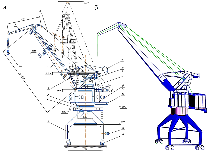
Fig. 1. General view of the KPP 16/32t crane at boom departures of 10-30 m and 10-20 m: a – actual design: 1 – portal;
2 – pivoting device; 3 – boom departure change mechanism; 4 – boom; 5 – cargo ropes and suspension of the main lift;
6 – portal head shells; 7 – trunk; 8 – flexible guy ropes; 9 – load of a movable counterweight on a rocker arm; 10 – load capacity limiter; 11 – frame; 12 – frame head; 13, 14 – mechanisms of closing and supporting winches; 15 – rotary platform;
16 – cable current supply mechanism; 17 – crane movement mechanism (4 pcs.); b – computer structural model
In order to avoid the uncertainties that arise when connecting rod and plate end elements of the portal head at the nodes, it is proposed to represent plate (continuous) elements of the crane metal structure (Fig. 2, a) with rod analogues (Fig. 2, b), which is typical for portal cranes of the Lenpodyemtransmash plant of the type of KPP 16/20t and KPP 16/32t (Fig. 3), in which the portal head is made in the form of 2 axisymmetric shells (Fig. 2), assembled in the mounting mode from two halves with diametrically arranged internal vertical flanges.


a b
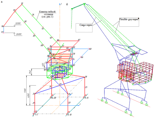
Fig. 2. Rod interpretation of the continuous shell system of the portal head of the portal crane of the KPP 16/32t:
a – shell parameters; b – rod interpretation by finite elements 34-35, and further, up to 64-65 (x, y, z – local coordinate system)
a b
Fig. 3. Finite element calculation and static model of the portal crane of the KPP 16/32t:
a – nodes U = 97, degrees of freedom n = 6U = 582;
b – the same, taking into account the finite element interpretation of the crane machine
Obviously, the process of discretization of continuous elements of the crane's metal structure should take into account that elastic-gravitational finite-element design models of lifting cranes are evaluated by the restoring forces of 2 fields: elastic, depending on the stiffness characteristics of the bearing elements of metal structures and gravitational, whose restoring forces are the gravitational gravity of the payload transported by the crane on a flexible rope polispast suspension with a height of 20 meters or more, loads of mechanisms, movable and fixed counterweights, etc.
The core interpretation of the continuous shells of the portal head and the development of a calculated static model of the crane
If we take a massive rod as the basis for finite element modeling of a crane, as a system with many degrees of freedom n = 6U = 6 · 97 = 582, where U = 97 – is the number of nodes of the calculated static model (Fig. 3), each node has 6 degrees of freedom
![]()
where δ – are translational; φ and θ – are rotational degrees of freedom of the terminal cross sections of the finite elements relative to the axes of the local xyz coordinate system of each finite element (Fig. 3); T – is the transposition index.
Then the finite element model of the crane in the general coordinate system will be determined by the coordinate vector of the nodes
{xyz}1U = {(xyz)1(xyz)2 …(xyz)j …(xyz)U}T,
and for each jk finite elements of the model, a vector of source data will be generated
{S}jk = {L, A, E, G, Ix, Iy, Iρ, v}T,
where S – is the number of finite elements of the model, then, respectively, length, cross-sectional area, elastic and shear modulus; {S}jk – are moments of inertia; v – is the Poisson's ratio.
Since the heads of the portals of cranes of the KPP type are made of sheet steel (Fig. 2, a), they should be modeled with plates [16], or plate structures should be modeled with conditional rods, which is considered appropriate when performing verification calculations of cranes for static and dynamic loads accepted according to GOST [20].
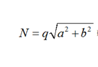
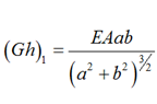
Here, in Fig. 2, b, the vertical walls of axisymmetric cylindrical shells are represented by vertical rods emanating from the corners of hexagons modeling the bottom of the portal head, whose geometric characteristics 34-46 and 40-52, 35-47 and 41-53, 36-48 and 42-54, 37-49 and 43-55, 38-50 and 44-56, 39-51 and 45-57 – moments of inertia Jх, Jy, Jρ and the area A of the cross sections of which are calculated according to the formulas proposed and tested in [21]:
 (2)
(2)
where b1 – is the distance between the vertical conditional rods (2.84 m); h1 – is the thickness of the vertical walls of the shells; v – is the Poisson's ratio.
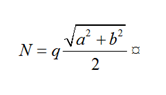
The lower plane of the paired shells is represented by conditional rods that are chords of circles: 34-35 and 40-41, 35-36 and 41-42, 36-37 and 42-43, 37-38 and 43-44, 38-39 and 44-45, 34-39 and 40-45, and the upper plane symmetrical to it are interpreted by conditional rods whose geometric characteristics, according to the method [21], have the form:
 (3)
(3)
where – is the linear size of the radius of the lower or upper bottom; H = 2.14 m is the height of the shells; h2 – is the thickness of the lower or upper bottom.
In addition to the vertical and circumferential conditional rods, we indicate that the radial rods, the lower: 34-40, 35-41, 36-42, 37-43, 38-44 and 39-45 and the upper ones symmetrical to them, belonging to the portal in the notation of formulas (2) and (3) have the form:

Additionally, we note that the models of the rods of the lower plane of the rotating part of the upper structure of the crane 58-59-...-63 hinge on the upper plane of the portal shells with rods 46-58, 47-59, ..., 51-63 and are centered in the rotation mode of the upper structure by the central trunnion 64-65, rigidly pinched into the portal head at node 64 (Fig. 2, b).
To account for rigidity diagonal rod elements must be introduced for the shift of the side rod panels of model hexagons (Fig. 2, b is not shown), the parameters of which, at the choice of the calculator, are accepted according to the recommendations [22] given in Table.
Interpretation of the shear stiffness of plate elements of cylindrical shells of the portal head*
|
No. |
Panel diagram |
Longitudinal force in the grid |
Equivalent shear stiffness |
|
1 |
 |
 |
 |
|
2 |
 |
 |
 |
|
3 |
 |
 |
 |
* h – is the thickness of the wall or bottom; q – is the distributed load.
Finite element computational analysis of the computational and static crane model KPP 16/32т
Now, after presenting the actual design of the KPP 16/32 crane with rod end elements, we write down a matrix equation of static equilibrium similar to (1)
![]() (4)
(4)
where [K]n×n – is the stiffness matrix of the complete crane system (Fig. 3) in the general xyz coordinate system, in the formation of which the stiffness matrices of individual jk finite elements using the transformation matrix ![]() are translated from the local coordinate system inherent in each finite element into the general coordinate system, after which the matrix [K]n×n in (4) is formed by the superposition method
are translated from the local coordinate system inherent in each finite element into the general coordinate system, after which the matrix [K]n×n in (4) is formed by the superposition method
 (5)
(5)
where T – is the transposition index; n = 582 is the number of degrees of freedom of the model (Fig. 3).
Here we also indicate that the matrix ![]() in expression (5) is diagonal:
in expression (5) is diagonal:
![]()
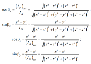
where [Ù]3×3 – the matrix of a linear transformation of the basis of the local coordinate system is at the basis of a common system of coordinates is defined by the Euler angles (Fig. 4) [23].

Fig. 4. Transition from the local coordinate system to the general coordinate system of finite elements jk
If the angles βx and βy are obvious in Fig. 4, then γB – is the angle of pure rotation, then the matrix [Ù]3×3 will take the form:
 (6)
(6)
The trigonometric values of the angles βx and βy in (6), expressed in terms of the coordinates of the beginning and end of the finite elements jk – хj,k, yj,k and zj,k, in the general coordinate system оxyz, its length ljk and the length of its projection onto the plane zох – (ljk)zох are determined by the formulas:
The displacement vector of the nodes of the computational static model {v}1×n in the matrix equation (4) is formed taking into account (1) and is determined by the number of degrees of freedom n = 6U, where U – is the number of nodes of the model, which, as it follows from Fig. 3, is set by the designer (calculator).
The load vector {Pst}1×n in equation (4) of the n-th order is formed according to GOST [20], where all loads are reduced to degrees of freedom of the computational static model.
For the purposes of forming the stiffness matrix of the complete system in (4), the stiffness matrix of a separate jk element ![]() in (5) is represented blockwise
in (5) is represented blockwise
 (7)
(7)
in which each of the blocks in (7) of finite elements jk occupies a place in the complete matrix [K]n×n according to the numbering of the degrees of freedom of nodes j and k, while the blocks in (7) have the form of matrix formulas in which ![]()


 (8)
(8)
 (9)
(9)
Conclusion
Two factors are taken into account when designing a rod finite element design and static model of a checkpoint crane, the brands of which were designed and mastered by production according to a single technical task and are currently operated in river and sea ports of Russia and CIS countries.
First, if the designer of portal cranes needs internal efforts in each jk finite element to make any verification decisions, then they are determined after solving equation (4), for example, by the Gauss method [24], then, after isolating from the general solution ![]() the displacements of the nodes of individual jk finite elements elements
the displacements of the nodes of individual jk finite elements elements ![]() and their translation from the general coordinate system to the local coordinate system the internal forces in each jk finite element, taking into account (8), are determined by the matrix formula (9).
and their translation from the general coordinate system to the local coordinate system the internal forces in each jk finite element, taking into account (8), are determined by the matrix formula (9).
The second factor obliges the designer to take into account the characteristics of the nodes, which, unlike the rigid fictitious finite element connections imposed on them, can be spherical or cylindrical hinges, complete or relative to individual axes of охyz. In this case, the blocks of the stiffness matrix (7) must be transformed by the method of the well-known Jordan new exceptions, taking into account the nature of the connections in the nodes of the computational static model, which differ from the elastic fictitious pinches inherent in the matrix (7) [25].
In addition, it should be emphasized that the rod finite element design and static model of the KPP 16/32t crane proposed in the article can be presented comprehensively, where, along with rod end elements, 2-dimensional plate end elements should be used for the portal head shells, as is customary in particular in [26], for span beams of bridge cranes, where the justification for the compatibility of one-dimensional and two-dimensional finite elements is accepted according to [1].
1. Perel'muter A. V., Slivker V. I. Raschetnye modeli sooruzhenii i vozmozhnost' ikh analiza [Design models of structures and the possibility of their analysis]. Moscow, DMK Publ., 2007. 600 p.
2. Evzerov I. D. Otsenki pogreshnosti po peremeshcheniiam pri ispol'zovanii nesovmestnykh konechnykh elementov [Estimates of the displacement error when using incompatible finite elements]. Chislennye metody mekhaniki sploshnoi sredy, 1983, vol. 14, no. 5, pp. 24-31.
3. Karpilovskii V. S. Issledovanie i konstruirovanie nekotorykh tipov konechnykh elementov dlia zadach stroitel'noi mekhaniki: dis. kand. tekhn. nauk [Research and design of some types of finite elements for problems of structural mechanics: dis. Candidate of Technical Sciences]. Kiev, 1982. 179 p.
4. Miachenkov V. I., Mal'tsev V. P., Maiboroda V. P. i dr. Raschety mashinostroitel'nykh konstruktsii metodom konechnykh elementov [Calculations of machine-building structures by the finite element method]. Moscow, Mashinostroenie Publ., 1989. 520 p.
5. Shimkovich D. G. Raschet konstruktsii v MSC/NASTRAN for Windows [Calculation of structures in MSC/NASTRAN for Windows]. Moscow, DMK Press, 2001. 448 p.
6. Shimkovich D. G. Femap&Nastran. Inzhenernyi analiz metodom konechnykh elementov [Engineering analysis by the finite element method]. Moscow, DMK Press, 2008. 704 p.
7. Postnov V. A., Kharkhurim I. Ia. Metod konechnykh elementov v raschetakh sudovykh konstruktsii [Finite element method in calculations of ship structures]. Leningrad, Sudostroenie Publ., 1974. 342 p.
8. Gol'denblat I. I., Bazhanov V. L. Fizicheskie i raschetnye modeli sooruzhenii [Physical and computational models of structures]. Stroitel'naia mekhanika i raschet sooruzhenii, 1970, no. 2, pp. 23-27.
9. Gorodetskii A. S., Evzerov I. D. Komp'iuternye modeli konstruktsii [Computer models of structures]. Kiev, Fakt Publ., 2005. 344 p.
10. Panovka Ia. G., Gubanova I. I. Ustoichivost' i kolebaniia uprugikh sistem: sovremennye kontseptsii, paradoksy i oshibki [Stability and oscillations of elastic systems: modern concepts, paradoxes and errors]. Moscow, Nauka Publ., 1987. 352 p.
11. Timoshenko S. P., Young D. H., Weaver W. Vibration Problems in Engineering. Wiley, Chichester, 1974. 538 p. (Timoshenko S. P., Iang D. Kh., Uiver U. Kolebaniia v inzhenernom dele / per. s angl. L. G. Korneichuka. M.: Mashinostroenie, 1985. 472 s.).
12. Nazarov D. Obzor sovremennykh programm konechno-elementnogo analiza [Overview of modern finite element analysis programs]. SAPR i grafika, 2000, no. 2, pp. 52-55.
13. Kaplun A. B., Morozov E. M., Olfer'eva M. A. ANSYS v rukakh inzhenera: prakticheskoe rukovodstvo [ANSYS in the hands of an engineer: a practical guide]. Moscow, Editorial URSS Publ., 2003. 272 p.
14. Panasenko N. N., Sinel'shchikov A. V. Metod konechnykh elementov v teorii seismostoikosti gruzopod"emnykh kranov: monografiia [The finite element method in the theory of seismic resistance of lifting cranes: monograph]. Astrakhan', Izd-vo AGTU, 2020. 376 p.
15. Panasenko N. N., Sinel'shchikov A. V. Konechno-elementnyi analiz i proektirovanie pod"emnykh sooruzhenii v seismostoikom ispolnenii: monografiia [Finite element analysis and design of lifting structures in earthquake-resistant design: monograph]. Moscow, ACV Publ., 2020. 760 p.
16. Panasenko N. N., Sinel'shchikov A. V. Matematicheskaia model' bazovykh konechnykh elementov v konechno-elementnoi teorii portovykh pod"emnykh sooruzhenii [Mathematical model of basic finite elements in the finite element theory of port lifting structures]. Vestnik Astrakhanskogo gosudarstvennogo tekhnicheskogo universiteta. Seriia: Morskaia tekhnika i tekhnologii, 2018, no. 1, pp. 109-128.
17. Matselia V. I., Seelev I. N., Lekontsev A. V., Khafizov R. R., Panasenko N. N., Sinel'shchikov A. V., Iakovlev P. V. Konechno-elementnaia raschetnaia model' promyshlennykh zdanii kak sistema tonkostennykh sterzhnei otkrytogo profilia [Finite element design model of industrial buildings as a system of thin-walled open-profile rods]. Mekhaniki XXI veku, 2017, no. 16, pp. 263-268.
18. Matselia V. I., Seelev I. N., Lekontsev A. V., Khafizov R. R., Panasenko N. N., Sinel'shchikov A. V., Iakovlev P. V. Raschetnyi analiz seismicheskoi bezopasnosti KhOT g. Zheleznogorska [Computational analysis of seismic safety of the HOT of Zheleznogorsk]. Novye materialy i tekhnologii v mashinostroenii: sbornik nauchnykh trudov, 2017, iss. 25, no. 25, pp. 111-129.
19. MR 1.5.2.05.999.0025-2011. Raschet i proektirovanie seismostoikikh atomnykh stantsii: metodicheskie rekomendatsii [Calculation and design of earthquake-resistant nuclear power plants: methodological recommendations]. Moscow, Rosenergoatom Publ., 2011. 92 p.
20. GOST 32579.1-2013. Krany gruzopod"emnye. Printsipy formirovaniia raschetnykh nagruzok i kombinatsii nagruzok. Part 1. Obshchie polozheniia [SS 32579.1-2013. Lifting cranes. Principles of formation of design loads and combinations of loads. Part 1. General provisions]. Moscow, Standartinform Publ., 2013. 15 p.
21. Issledovanie prochnosti i zhestkosti elementov oborudovaniia AES pri deistvii seismicheskikh nagruzok [Investigation of the strength and rigidity of NPP equipment elements under the action of seismic loads]. Otchet po NIR. Frunzenskii politekhnicheskii institut.; Avdeev V. I. i dr. Frunze, 1990. 127 p. N GR 800009724. Inv. № VNTITs 949901.
22. Boguslavskii P. E. Metallicheskie konstruktsii gruzopod"emnykh mashin i sooruzhenii [Metal structures of lifting machines and structures]. Moscow, Mashgiz Publ., 1961. 520 p.
23. Panasenko N. N., Bozhko S. G. Seismostoikie pod"emno-transportnye mashiny atomnykh stantsii: monografiia [Earthquake-resistant lifting and transport machines of nuclear power plants: monograph]. Krasnoiarsk, Izd-vo Krasnoiarskogo gosudarstvennogo universiteta, 1987. 208 p.
24. Forsythe G., Moler C. Computer solution of linear algebraic systems. Englewood Cliffs, NJ: Prentice-Hall, Inc., 1967. 148 p. (Forsait Dzh., Moler K. Chislennoe reshenie sistem lineinykh algebraicheskikh uravnenii / per. s angl. V. P. Il'ina i Iu. I. Kuznetsova. M.: Mir, 1969. 167 s.).
25. Klempert Iu. Z., Parikov V. I., Slivker V. I. O protsedure vychisleniia matritsy zhestkosti prizmaticheskogo sterzhnia [About the procedure for calculating the stiffness matrix of a prismatic rod]. Raschet prostranstvennykh konstruktsii, 1974, iss. XVI, pp. 179-189.
26. Sinel'shchikov A. V., Panasenko N. N. Sravnitel'nyi analiz raschetno-dinamicheskikh modelei portovykh kranov na osnove odno- i dvumernykh konechnykh elementov [Comparative analysis of computational and dynamic models of port cranes based on one- and two-dimensional finite elements]. Vestnik Astrakhanskogo gosudarstvennogo tekhnicheskogo universiteta. Seriia: Morskaia tekhnika i tekhnologii, 2019, no. 2, pp. 127-144.
