


Россия
Перегрузочные краны КПП завода «Ленподъемтрансмаш» широко используются в речных и морских портах, на промышленных предприятиях для грейферной перегрузки сыпучих грузов и для работы со штучными грузами или контейнерами, а также для перегрузки металлолома и металлопроката с помощью грузоподъемных электромагнитов. Предложено устранить неопределенности, обусловленные несовместимостью одномерных (стержневых) и двумерных (пластинчатых) конечных элементов, имеющих различное количество степеней свободы, 12 и 20, при разработке цифровых двойников портальных кранов завода «Ленподъемтрансмаш» на примере крана КПП 16/32т путем аппроксимации осесимметричных оболочек оголовка портала стержневыми конечными элементами. Метод основан на равенстве потенциальной энергии сдвига конечно-элементной модели пластины и потенциальной энергии аппроксимирующей стержневой модели, элементы которой работают на растяжение/сжатие, что позволило перейти от конечно-элементной модели перегрузочного крана КПП 16/32т, построенной на базовых конечных элементах пластин Кирхгофа, к конечно-элементной модели крана на основе стержневых базовых конечных элементов. Предложена математическая модель матричного уравнения статического равновесия со многими степенями свободы, численное решение которого методом Гаусса позволяет перейти к шестикомпонентным внутренним усилиям в каждом конечном элементе, обусловленным соответствующим вектором внешних нагрузок, приведенных к степеням свободы расчетной конечно-элементной модели. Исследована возможность интерпретации несущих элементов пространственных металлоконструкций портальных кранов как одномерными стержневыми, так и двумерными пластинчатыми конечными элементами, предложена переоценка традиционных взглядов на расчетный анализ напряженно-деформированного состояния металлоконструкций портальных кранов в области достоверного определения их несущей способности при эксплуатации в портах, особенно в области оценки послеремонтного риск-анализа и ресурса перегрузочных кранов, отработавших нормативный срок службы в порту и подвергнувшихся капитально-восстановительному ремонту. Построена расчетная стержневая конечно-элементная идеализированная модель портального крана КПП 16/32т для перевалки грузов в речных и морских портах, демонстрирующая переход от действительной конструкции к расчетной модели, в основу которого положены геометрические принципы дискретизации как стержневых, так и континуальных элементов базовыми стержневыми конечными элементами крана, в результате чего цифровая расчетная модель должна быть детальной и сложной, как система со многими степенями свободы. Приведен алгоритм применения цифровой расчетной модели крана на примере статического конечно-элементного расчетного анализа крана КПП 16/32т.
портальный кран, расчетная конечно-элементная модель, стержневой конечный элемент, дискретизация, степень свободы, матричное уравнение статического равновесия
Introduction
Considerable experience has been accumulated in the application of finite element theory in the computational analysis of machine-building and other types of structures based, as a rule, on four types of basic finite elements - rod (one-dimensional), plate, two-dimensional, tetrahedral and hexahedral - as three-dimensional finite elements, the basics of theory and practice of which are presented in a number of authoritative publications, among which the leading positions are considered to be assigned to the authors of several reprinted editions of the monograph by A. V. Perelmuter and V. I. Slivker [1], who, in their fundamental work, it is possible for the first time, following I. D. Evzerov [2], identified the problem of incompatible finite elements, which is repeated again in the works of the team of authors [3], in the reference monograph edited by V. I. Myachenkov [4], in chapter 2 “Finite element representation of models” by D. G. Shimkovich [5, 6], as well as in other well-known works on finite element modeling by V. A. Postnov and I. Ya. Kharkhurim [7], I. I. Goldenblat and V. L. Bazhanov [8], A. S. Gorodetsky and I. D. Evzerov [9] and others. In these works, taking into account the authoritative opinion of Y. G. Panovka [10], it is advisable to simplify the process of modeling structures, it is recommended to outline real plates with finite element Timoshenko rods [11] (see also [6]), or replace the plate with a finite element grid and “embed” into it the adjacent finite element structural element “rod” according to the principle “separation of the abutment area”. This interpretation of incompatible finite elements is obviously reflected in the programs of finite element analysis [12], including the well-known programs ANSYS [13] and CAD-2000 [14], including the work of D. G. Shimkovich [6] in relation to the computational analysis of “lifting type equipment”. However, in the works listed above, the transition from “qualitative” proposals to “quantitative” solutions was missed when switching from the parameters of continuum plates to their rod finite element interpretation in relation to the paired shells of the portal heads of Lenpodyemtransmash cranes operated in river and sea ports throughout Russia. Here, the authors of this work used the experience gained in the works [15-18] in the computational analysis of the spans of buildings with crane loads of domestic spent nuclear fuel storage facilities, made taking into account the requirements of the standard [19], which is what this article is devoted to.
Problem statement
The analysis of the rod system of the portal crane KPP 16/32t, (the final in the model series of cranes), as a system of finite elements, using the method of rod interpretation of the continuous shell bearing elements of the metal structures of the portal head of the crane and to develop a finite element calculated static model of the crane KPP 16/32t, based on an algorithmic model of its statistical calculation up to determination of the 12-component vector of internal forces in each finite element of the computational-static model.
The stiffness characteristics of the load-bearing elements of metal structures are determined depending on the basic finite elements used by the designer, which are the basis of the computational and static crane model, the central parameter of which is its stiffness matrix of the Kn-th order, where n is the number of degrees of freedom of the model equal to 6U, where U – the number of nodes of the discrete approximation of the continuum elements of the actual crane design (Fig. 1), which, within the limits of the correspondence of the finite element model of the crane (digital twin) to its actual design (Fig. 1, b) and the required accuracy of solving the static equilibrium equation of the n-th order
![]() (1)
(1)
it is determined by the compatibility of the finite elements used.
a b
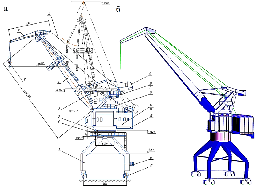
Fig. 1. General view of the KPP 16/32t crane at boom departures of 10-30 m and 10-20 m: a – actual design: 1 – portal;
2 – pivoting device; 3 – boom departure change mechanism; 4 – boom; 5 – cargo ropes and suspension of the main lift;
6 – portal head shells; 7 – trunk; 8 – flexible guy ropes; 9 – load of a movable counterweight on a rocker arm; 10 – load capacity limiter; 11 – frame; 12 – frame head; 13, 14 – mechanisms of closing and supporting winches; 15 – rotary platform;
16 – cable current supply mechanism; 17 – crane movement mechanism (4 pcs.); b – computer structural model
In order to avoid the uncertainties that arise when connecting rod and plate end elements of the portal head at the nodes, it is proposed to represent plate (continuous) elements of the crane metal structure (Fig. 2, a) with rod analogues (Fig. 2, b), which is typical for portal cranes of the Lenpodyemtransmash plant of the type of KPP 16/20t and KPP 16/32t (Fig. 3), in which the portal head is made in the form of 2 axisymmetric shells (Fig. 2), assembled in the mounting mode from two halves with diametrically arranged internal vertical flanges.


a b
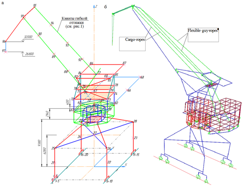
Fig. 2. Rod interpretation of the continuous shell system of the portal head of the portal crane of the KPP 16/32t:
a – shell parameters; b – rod interpretation by finite elements 34-35, and further, up to 64-65 (x, y, z – local coordinate system)
a b
Fig. 3. Finite element calculation and static model of the portal crane of the KPP 16/32t:
a – nodes U = 97, degrees of freedom n = 6U = 582;
b – the same, taking into account the finite element interpretation of the crane machine
Obviously, the process of discretization of continuous elements of the crane's metal structure should take into account that elastic-gravitational finite-element design models of lifting cranes are evaluated by the restoring forces of 2 fields: elastic, depending on the stiffness characteristics of the bearing elements of metal structures and gravitational, whose restoring forces are the gravitational gravity of the payload transported by the crane on a flexible rope polispast suspension with a height of 20 meters or more, loads of mechanisms, movable and fixed counterweights, etc.
The core interpretation of the continuous shells of the portal head and the development of a calculated static model of the crane
If we take a massive rod as the basis for finite element modeling of a crane, as a system with many degrees of freedom n = 6U = 6 · 97 = 582, where U = 97 – is the number of nodes of the calculated static model (Fig. 3), each node has 6 degrees of freedom
![]()
where δ – are translational; φ and θ – are rotational degrees of freedom of the terminal cross sections of the finite elements relative to the axes of the local xyz coordinate system of each finite element (Fig. 3); T – is the transposition index.
Then the finite element model of the crane in the general coordinate system will be determined by the coordinate vector of the nodes
{xyz}1U = {(xyz)1(xyz)2 …(xyz)j …(xyz)U}T,
and for each jk finite elements of the model, a vector of source data will be generated
{S}jk = {L, A, E, G, Ix, Iy, Iρ, v}T,
where S – is the number of finite elements of the model, then, respectively, length, cross-sectional area, elastic and shear modulus; {S}jk – are moments of inertia; v – is the Poisson's ratio.
Since the heads of the portals of cranes of the KPP type are made of sheet steel (Fig. 2, a), they should be modeled with plates [16], or plate structures should be modeled with conditional rods, which is considered appropriate when performing verification calculations of cranes for static and dynamic loads accepted according to GOST [20].
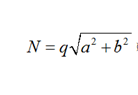
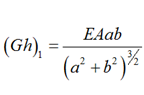
Here, in Fig. 2, b, the vertical walls of axisymmetric cylindrical shells are represented by vertical rods emanating from the corners of hexagons modeling the bottom of the portal head, whose geometric characteristics 34-46 and 40-52, 35-47 and 41-53, 36-48 and 42-54, 37-49 and 43-55, 38-50 and 44-56, 39-51 and 45-57 – moments of inertia Jх, Jy, Jρ and the area A of the cross sections of which are calculated according to the formulas proposed and tested in [21]:
 (2)
(2)
where b1 – is the distance between the vertical conditional rods (2.84 m); h1 – is the thickness of the vertical walls of the shells; v – is the Poisson's ratio.
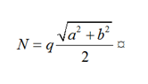
The lower plane of the paired shells is represented by conditional rods that are chords of circles: 34-35 and 40-41, 35-36 and 41-42, 36-37 and 42-43, 37-38 and 43-44, 38-39 and 44-45, 34-39 and 40-45, and the upper plane symmetrical to it are interpreted by conditional rods whose geometric characteristics, according to the method [21], have the form:
 (3)
(3)
where – is the linear size of the radius of the lower or upper bottom; H = 2.14 m is the height of the shells; h2 – is the thickness of the lower or upper bottom.
In addition to the vertical and circumferential conditional rods, we indicate that the radial rods, the lower: 34-40, 35-41, 36-42, 37-43, 38-44 and 39-45 and the upper ones symmetrical to them, belonging to the portal in the notation of formulas (2) and (3) have the form:

Additionally, we note that the models of the rods of the lower plane of the rotating part of the upper structure of the crane 58-59-...-63 hinge on the upper plane of the portal shells with rods 46-58, 47-59, ..., 51-63 and are centered in the rotation mode of the upper structure by the central trunnion 64-65, rigidly pinched into the portal head at node 64 (Fig. 2, b).
To account for rigidity diagonal rod elements must be introduced for the shift of the side rod panels of model hexagons (Fig. 2, b is not shown), the parameters of which, at the choice of the calculator, are accepted according to the recommendations [22] given in Table.
Interpretation of the shear stiffness of plate elements of cylindrical shells of the portal head*
|
No. |
Panel diagram |
Longitudinal force in the grid |
Equivalent shear stiffness |
|
1 |
 |
 |
 |
|
2 |
 |
 |
 |
|
3 |
 |
 |
 |
* h – is the thickness of the wall or bottom; q – is the distributed load.
Finite element computational analysis of the computational and static crane model KPP 16/32т
Now, after presenting the actual design of the KPP 16/32 crane with rod end elements, we write down a matrix equation of static equilibrium similar to (1)
![]() (4)
(4)
where [K]n×n – is the stiffness matrix of the complete crane system (Fig. 3) in the general xyz coordinate system, in the formation of which the stiffness matrices of individual jk finite elements using the transformation matrix ![]() are translated from the local coordinate system inherent in each finite element into the general coordinate system, after which the matrix [K]n×n in (4) is formed by the superposition method
are translated from the local coordinate system inherent in each finite element into the general coordinate system, after which the matrix [K]n×n in (4) is formed by the superposition method
 (5)
(5)
where T – is the transposition index; n = 582 is the number of degrees of freedom of the model (Fig. 3).
Here we also indicate that the matrix ![]() in expression (5) is diagonal:
in expression (5) is diagonal:
![]()
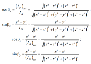
where [Ù]3×3 – the matrix of a linear transformation of the basis of the local coordinate system is at the basis of a common system of coordinates is defined by the Euler angles (Fig. 4) [23].

Fig. 4. Transition from the local coordinate system to the general coordinate system of finite elements jk
If the angles βx and βy are obvious in Fig. 4, then γB – is the angle of pure rotation, then the matrix [Ù]3×3 will take the form:
 (6)
(6)
The trigonometric values of the angles βx and βy in (6), expressed in terms of the coordinates of the beginning and end of the finite elements jk – хj,k, yj,k and zj,k, in the general coordinate system оxyz, its length ljk and the length of its projection onto the plane zох – (ljk)zох are determined by the formulas:
The displacement vector of the nodes of the computational static model {v}1×n in the matrix equation (4) is formed taking into account (1) and is determined by the number of degrees of freedom n = 6U, where U – is the number of nodes of the model, which, as it follows from Fig. 3, is set by the designer (calculator).
The load vector {Pst}1×n in equation (4) of the n-th order is formed according to GOST [20], where all loads are reduced to degrees of freedom of the computational static model.
For the purposes of forming the stiffness matrix of the complete system in (4), the stiffness matrix of a separate jk element ![]() in (5) is represented blockwise
in (5) is represented blockwise
 (7)
(7)
in which each of the blocks in (7) of finite elements jk occupies a place in the complete matrix [K]n×n according to the numbering of the degrees of freedom of nodes j and k, while the blocks in (7) have the form of matrix formulas in which ![]()


 (8)
(8)
 (9)
(9)
Conclusion
Two factors are taken into account when designing a rod finite element design and static model of a checkpoint crane, the brands of which were designed and mastered by production according to a single technical task and are currently operated in river and sea ports of Russia and CIS countries.
First, if the designer of portal cranes needs internal efforts in each jk finite element to make any verification decisions, then they are determined after solving equation (4), for example, by the Gauss method [24], then, after isolating from the general solution ![]() the displacements of the nodes of individual jk finite elements elements
the displacements of the nodes of individual jk finite elements elements ![]() and their translation from the general coordinate system to the local coordinate system the internal forces in each jk finite element, taking into account (8), are determined by the matrix formula (9).
and their translation from the general coordinate system to the local coordinate system the internal forces in each jk finite element, taking into account (8), are determined by the matrix formula (9).
The second factor obliges the designer to take into account the characteristics of the nodes, which, unlike the rigid fictitious finite element connections imposed on them, can be spherical or cylindrical hinges, complete or relative to individual axes of охyz. In this case, the blocks of the stiffness matrix (7) must be transformed by the method of the well-known Jordan new exceptions, taking into account the nature of the connections in the nodes of the computational static model, which differ from the elastic fictitious pinches inherent in the matrix (7) [25].
In addition, it should be emphasized that the rod finite element design and static model of the KPP 16/32t crane proposed in the article can be presented comprehensively, where, along with rod end elements, 2-dimensional plate end elements should be used for the portal head shells, as is customary in particular in [26], for span beams of bridge cranes, where the justification for the compatibility of one-dimensional and two-dimensional finite elements is accepted according to [1].
1. Перельмутер А. В., Сливкер В. И. Расчетные модели сооружений и возможность их анализа. М.: ДМК, 2007. 600 с.
2. Евзеров И. Д. Оценки погрешности по перемещениям при использовании несовместных конечных элементов // Числ. методы механики сплош. среды. 1983. Т. 14. № 5. С. 24-31.
3. Карпиловский В. С. Исследование и конструирование некоторых типов конечных элементов для задач строительной механики: дис. канд. техн. наук. Киев, 1982. 179 с.
4. Мяченков В. И., Мальцев В. П., Майборода В. П. и др. Расчеты машиностроительных конструкций методом конечных элементов. М.: Машиностроение, 1989. 520 с.
5. Шимкович Д. Г. Расчет конструкций в MSC/NASTRAN for Windows. М.: ДМК Пресс, 2001. 448 с.
6. Шимкович Д. Г. Femap&Nastran. Инженерный анализ методом конечных элементов. М.: ДМК Пресс, 2008. 704 с.
7. Постнов В. А., Хархурим И. Я. Метод конечных элементов в расчетах судовых конструкций. Л.: Судостро-ение, 1974. 342 с.
8. Гольденблат И. И., Бажанов В. Л. Физические и расчетные модели сооружений // Строит. механика и расчет сооружений. 1970. № 2. С. 23-27.
9. Городецкий А. С., Евзеров И. Д. Компьютерные модели конструкций. Киев: Факт, 2005. 344 с.
10. Пановка Я. Г., Губанова И. И. Устойчивость и колебания упругих систем: современные концепции, парадоксы и ошибки. М.: Наука, 1987. 352 с.
11. Тимошенко С. П., Янг Д. Х., Уивер У. Колебания в инженерном деле / пер. с англ. Л. Г. Корнейчука. М.: Машиностроение, 1985. 472 с.
12. Назаров Д. Обзор современных программ конечно-элементного анализа // САПР и графика. 2000. № 2. С. 52-55.
13. Каплун А. Б., Морозов Е. М., Олферьева М. А. ANSYS в руках инженера: практическое руководство. М.: Едиториал УРСС, 2003. 272 с.
14. Панасенко Н. Н., Синельщиков А. В. Метод конечных элементов в теории сейсмостойкости грузоподъемных кранов: моногр. Астрахань: Изд-во АГТУ, 2020. 376 с.
15. Панасенко Н. Н., Синельщиков А. В. Конечно-элементный анализ и проектирование подъемных сооружений в сейсмостойком исполнении: моногр. М.: АCВ, 2020. 760 с.
16. Панасенко Н. Н., Синельщиков А. В. Математическая модель базовых конечных элементов в конечно-элементной теории портовых подъемных сооружений // Вестн. Астрахан. гос. техн. ун-та. Сер.: Морская техника и технологии. 2018. № 1. С. 109-128.
17. Мацеля В. И., Сеелев И. Н., Леконцев А. В., Хафизов Р. Р., Панасенко Н. Н., Синельщиков А. В., Яковлев П. В. Конечно-элементная расчетная модель промышленных зданий как система тонкостенных стержней открытого профиля // Механики XXI веку. 2017. № 16. С. 263-268.
18. Мацеля В. И., Сеелев И. Н., Леконцев А. В., Хафизов Р. Р., Панасенко Н. Н., Синельщиков А. В., Яковлев П. В. Расчетный анализ сейсмической безопасности ХОТ г. Железногорска // Новые материалы и технологии в машиностроении: сб. науч. тр. 2017. Вып. 25. № 25. С. 111-129.
19. МР 1.5.2.05.999.0025-2011. Расчет и проектирование сейсмостойких атомных станций: метод. рекомендации. М.: Росэнергоатом, 2011. 92 с.
20. ГОСТ 32579.1-2013. Краны грузоподъемные. Принципы формирования расчетных нагрузок и комбинаций нагрузок. Ч. 1. Общие положения. М.: Стандартинформ, 2013. 15 с.
21. Исследование прочности и жесткости элементов оборудования АЭС при действии сейсмических нагрузок: отчет по НИР / Фрунзен. политехн. ин-т.; Авдеев В. И. и др. Фрунзе, 1990. 127 с. № ГР 800009724. Инв. № ВНТИЦ 949901.
22. Богуславский П. Е. Металлические конструкции грузоподъемных машин и сооружений. М.: Машгиз, 1961. 520 с.
23. Панасенко Н. Н., Божко С. Г. Сейсмостойкие подъемно-транспортные машины атомных станций: моногр. Красноярск: Изд-во Красноярс. гос. ун-та, 1987. 208 с.
24. Форсайт Дж., Молер К. Численное решение систем линейных алгебраических уравнений / пер. с англ. В. П. Ильина и Ю. И. Кузнецова. М.: Мир, 1969. 167 с.
25. Клемперт Ю. З., Париков В. И., Сливкер В. И. О процедуре вычисления матрицы жесткости призматического стержня // Расчет пространств. конструкций. 1974. Вып. XVI. С. 179-189.
26. Синельщиков А. В., Панасенко Н. Н. Сравнительный анализ расчетно-динамических моделей портовых кранов на основе одно- и двумерных конечных элементов // Вестн. Астрахан. гос. техн. ун-та. Сер.: Морская техника и технологии. 2019. № 2. С. 127-144.
