


Russian Federation
from 01.01.2019 until now
from 01.01.2014 to 01.01.2020
Petropavlovsk-Kamchatskiy, Kamchatka, Russian Federation
Russian Federation
UDC 629.5.023
In accordance with the requirements of regulatory and technical documents on ships, it is necessary to apply protective protection to prevent contact corrosion of ship systems, apparatuses and equipment when using dissimilar materials, as well as selective and pitting corrosion. It is recommended to make protectors from the following materials: zinc Zn, aluminum Al and steel grade ST-3 or South. On many ships of the Kamchatka Fleet, factory-made zinc and steel protectors are used to protect ship structures (steel hulls and elements of the ship's power plant) from corrosion, as well as steel protectors of their own design and manufacture by the shipowner's mechanical service or at the ship repair plant, which are approved and approved for use on ships by classification societies. At the same time, many ship mechanics of the Kamchatka Fleet face the problem of conducting input technical control of the operability of steel treads supplied for replacement, since there is a lack of appropriate monitoring equipment, methods and competencies. The manual control procedure is time-consuming, complex and has a high risk of obtaining unreliable results due to the influence of errors and human factors. The necessity of developing an affordable and reliable method of technical control of shipboard steel protectors of factory and non-factory manufacture, which can be used by the ship's mechanical service, is substantiated. The description of the developed author's technical method of non-destructive testing of the technical condition of steel treads, which can be implemented on ships by ship crews, is given. To monitor the projector protection, an automated measuring system has been developed, the structure and principle of operation of which are discussed in other articles by the authors. The technical condition of three steel protectors (one factory-made, two manufactured by the shipowner's mechanical service) used on the RS-70 vessel to protect the vessel from corrosion was monitored. It has been established that factory-made protectors and protectors manufactured by marine mechanical services can be used on ships, but to increase reliability, it is recommended to use additional input control according to the developed author's methodology.
steel protectors of marine vessels, silver chloride reference electrode, measurement of protector potentials, measurement of protector protective current, cell for non-destructive testing of marine protectors
Introduction
In accordance with regulatory requirements [1-5], sea-going vessels must employ protector systems to prevent: a) contact corrosion of ship systems, apparatus, and equipment when dissimilar materials are used, and b) selective and pitting corrosion. Protectors are manufactured from the following materials [1]: a) Zn, b) Al, c) steel (grades ST-3 or YuZ).
On many vessels of the Kamchatka fleet, zinc and steel protectors [1] are used to protect ship structures (steel hulls and marine propulsion plant (MPP) components). These include factory-made products as well as steel protectors produced by shipowners’ marine engineering services or by specialists at ship-repair yards. For many ship mechanics in the Kamchatka fleet, the use of self-made steel protectors raises questions. As a result, the mechanics of the auxiliary vessel RS-70 approached the Department of “Power Plants and Electrical Equipment of Ships” at Kamchatka State Technical University with a request to implement on their vessel an automated method for incoming non-destructive testing of the technical condition of ship steel protectors, which has been patented [6].
The purpose of this article is to investigate the necessity and feasibility of implementing on sea-going vessels a non-destructive method for assessing the technical condition of steel protectors used for corrosion protection.
To achieve this goal, the authors carried out a series of experimental studies, the essence of which is presented below.
Experimental part
To obtain a sample of results sufficient for analysis, the technical condition of three steel protectors used on the RS-70 vessel to protect MPP components from corrosion was monitored. Three protectors were tested (No. 1 – factory-made; No. 2 and 3 – manufactured by the ship’s mechanical service), the general view of which is shown in Fig. 1.
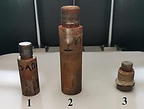
Fig. 1. General view of the steel protectors under study: 1 – factory-made steel protector (No. 1);
2 – self-made steel protector (No. 2); 3 – self-made steel protector (No. 3)
At the first stage, the operating potentials of the steel protectors (1-3) were measured using a standard silver chloride reference (SCR) electrode [7]. A second-class reference electrode with a ShP 4-2 plug manufactured in GOMEL was used as the standard SCR. This SCR is shown in Fig. 2.
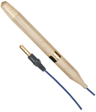
Fig. 2. Second-class reference electrode with ShP 4-2 plug manufactured by GOMEL (general view)
Control measurements were carried out using the authors’ cell for non-destructive testing of the electrochemical properties of marine protectors [6], whose design is shown in Fig. 3.
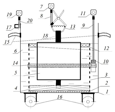
Fig. 3. Cell design for non-destructive testing of the electrochemical properties of marine protectors:
1 – steel tank; 2 – adhesive joint; 3 – perforated dielectric container; 4 – resilient dielectric gasket;
5 – replaceable test protector; 6 – seawater; 7, 11, 19 – measuring cable lug; 8, 9, 20 – measuring cable;
10 – reference electrode; 12 – dielectric float; 13 – spring-loaded self-clamping “crocodile” contact;
14 – rubber clamping ring; 15 – steel handles; 16 – wheels; 17 – bolted joint; 18 – steel fittings
The device was operated and the non-destructive inspection of individual ship protectors was performed as follows:
– an uncoated steel tank is filled with natural or artificial seawater to the specified mark;
– the test protector is placed vertically in the perforated dielectric container and fixed in position using the dielectric float;
– a measuring cable with a crimp lug is connected to the steel fitting of the protector using the clamping contact;
– 15 minutes after immersing the test protector in seawater, the potential difference (ΔU) between the protector and the reference electrode is measured with a millivoltmeter;
– after measuring the potential difference between the test protector and the reference electrode, the current in the measuring circuit formed by the protector under test, the ammeter, the uncoated steel tank and seawater is measured with an ammeter.
Figure 4 shows a general view of an automated device for non-destructive testing of the electrochemical properties of marine vessel protectors.
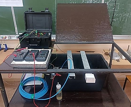
Fig. 4. Automated device for non-destructive testing of the technical condition of marine protectors (general view)
For each of the three protectors in the device shown in Fig. 4, 50 individual control measurements (a representative sample) of the potential of each steel protector (U1, U2, U3, mV) were taken at 1-minute intervals. The results were processed in MS Excel using standard methods of mathematical statistics. The following were calculated for statistical processing:
a) mathematical expectation (arithmetic mean); b) coefficient of variation; c) variance of the measurement results to assess the quality of the sample.
At the second stage, the protective current (I1, I2, I3, mA) was measured in the electrical circuits formed by the individual steel protector (anode), seawater, a stainless-steel cathode [6], and the measuring device. For each circuit, 50 individual current measurements (I, mA) were taken at 1-minute intervals.
Results and discussion
The results of the control measurements and their statistical processing are presented in the Table below.
Results of non-destructive testing of the technical condition of steel protectors
|
№ |
U1, mV |
U2, mV |
U3, mV |
I1, mA |
I2, mA |
I3, mA |
|
1 |
644 |
621 |
672 |
14 |
16 |
18 |
|
2 |
644 |
620 |
672 |
14 |
13 |
13 |
|
3 |
644 |
620 |
672 |
11 |
10 |
12 |
|
4 |
644 |
620 |
671 |
10 |
8 |
11 |
|
5 |
643 |
621 |
671 |
10 |
10 |
11 |
|
6 |
643 |
621 |
672 |
10 |
9 |
10 |
|
7 |
643 |
621 |
673 |
10 |
8 |
10 |
|
8 |
643 |
621 |
672 |
7 |
7 |
11 |
|
9 |
644 |
623 |
672 |
8 |
8 |
9 |
|
10 |
644 |
623 |
684 |
8 |
8 |
10 |
|
11 |
646 |
626 |
679 |
7 |
8 |
10 |
|
12 |
645 |
629 |
678 |
9 |
7 |
9 |
|
13 |
645 |
628 |
676 |
7 |
7 |
9 |
|
14 |
645 |
630 |
675 |
8 |
7 |
11 |
|
15 |
644 |
630 |
678 |
7 |
7 |
10 |
|
16 |
644 |
630 |
674 |
8 |
8 |
11 |
|
17 |
646 |
629 |
671 |
7 |
7 |
9 |
|
18 |
647 |
629 |
668 |
8 |
7 |
9 |
|
19 |
642 |
628 |
674 |
9 |
8 |
11 |
|
20 |
646 |
629 |
676 |
8 |
7 |
11 |
|
21 |
646 |
629 |
680 |
9 |
9 |
8 |
|
22 |
645 |
630 |
689 |
9 |
10 |
9 |
|
23 |
645 |
630 |
662 |
8 |
8 |
8 |
|
24 |
645 |
631 |
669 |
7 |
7 |
9 |
|
25 |
645 |
632 |
675 |
8 |
7 |
8 |
|
26 |
642 |
632 |
676 |
7 |
7 |
10 |
|
27 |
642 |
633 |
678 |
7 |
6 |
8 |
|
28 |
642 |
633 |
679 |
8 |
7 |
10 |
|
29 |
642 |
634 |
679 |
7 |
7 |
8 |
|
30 |
642 |
633 |
680 |
6 |
7 |
10 |
|
31 |
642 |
636 |
680 |
11 |
7 |
12 |
|
32 |
642 |
635 |
681 |
10 |
10 |
10 |
|
33 |
643 |
636 |
683 |
9 |
9 |
10 |
|
34 |
643 |
636 |
683 |
8 |
9 |
8 |
|
35 |
647 |
636 |
682 |
10 |
7 |
9 |
|
36 |
647 |
637 |
682 |
8 |
9 |
9 |
|
37 |
649 |
637 |
682 |
8 |
8 |
9 |
|
38 |
649 |
636 |
680 |
9 |
7 |
7 |
|
39 |
649 |
636 |
681 |
9 |
7 |
9 |
|
40 |
649 |
637 |
681 |
10 |
7 |
9 |
|
41 |
649 |
637 |
682 |
10 |
8 |
8 |
|
42 |
650 |
637 |
683 |
9 |
7 |
7 |
|
43 |
650 |
637 |
684 |
8 |
8 |
10 |
|
44 |
647 |
638 |
683 |
8 |
7 |
8 |
|
45 |
647 |
637 |
683 |
8 |
8 |
10 |
|
46 |
646 |
637 |
688 |
7 |
8 |
8 |
|
47 |
645 |
637 |
689 |
9 |
9 |
8 |
|
48 |
644 |
638 |
685 |
8 |
7 |
10 |
|
49 |
642 |
638 |
682 |
7 |
7 |
8 |
|
50 |
647 |
638 |
684 |
8 |
8 |
9 |
|
Mean |
644.98 |
631.04 |
678.10 |
8.60 |
8.04 |
9.62 |
|
Range |
8.00 |
18.00 |
27.00 |
8.00 |
10.00 |
11.00 |
|
Standard deviation |
1.90 |
5.04 |
4.77 |
1.22 |
1.06 |
1.24 |
|
Variance |
5.46 |
35.36 |
32.73 |
2.56 |
2.76 |
3.12 |
|
Standard deviation |
2.36 |
6.01 |
5.78 |
1.62 |
1.68 |
1.78 |
|
Coefficient of variation |
0.37 |
0.95 |
0.85 |
18.79 |
20.87 |
18.53 |
From the results shown in the Tables, the following can be concluded:
– the control measurements of protector potentials for all specimens are classified as precise based on the coefficient of variation Kvar 1-3 < 1% [8];
– the expected higher quality of the factory-made protector No. 1 is confirmed by its lower standard deviation for both U and I parameters. The standard deviation for specimen No. 1 is 2.5× lower for U parameter (relative to specimen No. 2) and 1.1× lower for I (relative to specimen No. 3);
– steel protectors manufactured by a ship’s mechanical service can be used on sea-going vessels after control tests, since their inspection results satisfy the requirements of the normative document [1].
The mean potential parameters of steel protectors No. 2 and 3 (workshop-made) lie within the same intervals as those of the factory protector No. 1:
│U1avg – U2avg│= 13.94 < 50 mV;
│U1avg – U3avg│= 33.14 < 50 mV
at R1-3 < 30 mV.
Conclusion
The following conclusions can be drawn from the completed study:
1. Sea-going vessels should implement incoming non-destructive testing of the technical condition of steel protectors, both for products manufactured at specialized facilities and for protectors made by shipowners’ mechanical services or by ship-repair specialists.
2. Implementing the incoming testing method will allow for an objective justification for the use of steel protectors, including those manufactured in-house.
3. The manufacturing quality of the factory-made steel protector is higher than that of the workshop-made items; however, for all specimens the coefficient of variation over 50 measurements is below 25%: the maximum values are 0.95% for U and 20.87% for I (specimen No. 2).
4. The use of incoming testing of steel protectors requires the development of automated measuring systems to minimize measurement errors and reduce the impact of the human factor on the part of ship crews.
1. RD 31.28.10-97. Kompleksnye metody zashchity sudovyh konstrukcij ot korrozii [RD 31.28.10-97. Comprehensive methods of protection of ship structures from corrosion]. Moscow, Izd-vo CNIIMF, 1997. 169 p.
2. GOST 9.056-75. Stal'nye korpusa korablej i sudov. Obshchie trebovaniya k elektrohimicheskoj zashchite [ISS 9.056-75. Steel hulls of ships and vessels. General requirements for electrochemical protection]. Moscow, Izd-vo standartov, 1986. 20 p.
3. GOST 26501-85. Korpusa morskih sudov. Obshchie trebovaniya k elektrohimicheskoj zashchite [ISS 26501-85. The hulls of naval vessels. General requirements for electro-chemical protection]. Moscow, Izd-vo standartov, 1985. 7 p.
4. RZK-NK-01. Rukovodstvo po zashchite korpusov nadvodnyh korablej VMF ot korrozii i obrastaniya [RZK-NK-01. Guidelines for protecting Naval Surface Ship hulls from corrosion and fouling]. Moscow, Voennoe izd-vo, 2001. 258 p.
5. Chandler K. A. Marine and offshore corrosion. London, Butterworth, 1984. 413 p. (Chendler K. A. Korroziya sudov i morskih sooruzhenij / per. s angl. I. A. Barhatova, V. I. Lemkova. L.: Sudostroenie, 1988. 320 s.).
6. Yastrebov D. P., Rogozhnikov A. O., Novosadov B. I., Kruten' Yu. V. Yachejka dlya nerazrushayushchego kontrolya elektrohimicheskih svojstv protektorov morskih sudov [A cell for non-destructive testing of electrochemical properties of marine protectors]. atent RF, no. 2023109231, 05.12.2023.
7. GOST 17792-72. Elektrod sravneniya hlorserebryanyj nasyshchennyj obrazcovyj 2-go razryada [ISS 17792-72. Silver chloride saturated reference electrode of the 2nd category]. Moscow, Izd-vo standartov, 1972. 9 p.
8. Smagunova A. N., Karpukova O. M. Metody ma-tematicheskoj statistiki v analiticheskoj himii: uchebnoe posobie [Methods of mathematical statistics in analytical chemistry: a textbook]. Irkutsk, Izd-vo IGU, 2008. 339 p.
