


Россия
с 01.01.2019 по настоящее время
с 01.01.2014 по 01.01.2020
Петропавловск-Камчатский, Камчатский край, Россия
Россия
УДК 629.5.023 Корпус, набор корпуса и корпусные элементы
В соответствии с требованиями нормативно-технических документов на морских судах необходимо применять протекторную защиту для предотвращения контактной коррозии судовых систем, аппаратов и оборудования при использовании разнородных материалов, а также избирательной и питтинговой коррозии. Рекомендуется изготавливать протекторы из следующих материалов: цинк Zn, алюминий Al и сталь марки СТ-3 или ЮЗ. На многих морских судах Камчатского флота для защиты от коррозии судовых конструкций (корпуса из стали и элементов судовой энергетической установки) используют цинковые и стальные протекторы заводского изготовления, а также стальные протекторы собственной разработки и изготовления судомеханической службой судовладельца или на судоремонтном заводе, допускаемых и согласованных к применению на судах со стороны классификационных обществ. При этом у многих судовых механиков Камчатского флота возникает проблема проведения входного технического контроля работоспособности поставляемых для замены стальных протекторов, поскольку отсутствуют соответствующая аппаратура контроля, методика и компетенции. Процедура ручного контроля трудоемка, сложна и имеет высокий риск получения недостоверных результатов из-за влияния погрешностей и человеческого фактора. Обоснована необходимость разработки доступного и надежного в эксплуатации метода технического контроля судовых стальных протекторов заводского и незаводского изготовления, который может использовать судомеханическая служба судна. При-ведено описание разработанного авторского технического способа неразрушающего контроля технического состояния стальных протекторов, который может быть внедрен экипажами на морских судах. Для проведения контроля проекторной защиты разработана автоматизированная измерительная система, конструкция и принцип действия которой рассматривается в других статьях авторов. Проведен контроль технического состояния трех стальных протекторов (один – заводского исполнения, два – изготовленных судомеханической службой судовладельца), используемых на судне РС-70 для защиты от коррозии судна. Установлено, что протекторы заводского исполнения и протекторы, изготовленные судомеханическими службами, могут быть использованы на судах, но для повышения надежности рекомендуется использовать дополнительный входной контроль по разработанной авторской методике.
стальные протекторы морских судов, хлорсеребряный электрод сравнения, измерение потенциалов протектора, измерение защитного тока протектора, ячейка для неразрушающего контроля протекторов морских судов
Introduction
In accordance with regulatory requirements [1-5], sea-going vessels must employ protector systems to prevent: a) contact corrosion of ship systems, apparatus, and equipment when dissimilar materials are used, and b) selective and pitting corrosion. Protectors are manufactured from the following materials [1]: a) Zn, b) Al, c) steel (grades ST-3 or YuZ).
On many vessels of the Kamchatka fleet, zinc and steel protectors [1] are used to protect ship structures (steel hulls and marine propulsion plant (MPP) components). These include factory-made products as well as steel protectors produced by shipowners’ marine engineering services or by specialists at ship-repair yards. For many ship mechanics in the Kamchatka fleet, the use of self-made steel protectors raises questions. As a result, the mechanics of the auxiliary vessel RS-70 approached the Department of “Power Plants and Electrical Equipment of Ships” at Kamchatka State Technical University with a request to implement on their vessel an automated method for incoming non-destructive testing of the technical condition of ship steel protectors, which has been patented [6].
The purpose of this article is to investigate the necessity and feasibility of implementing on sea-going vessels a non-destructive method for assessing the technical condition of steel protectors used for corrosion protection.
To achieve this goal, the authors carried out a series of experimental studies, the essence of which is presented below.
Experimental part
To obtain a sample of results sufficient for analysis, the technical condition of three steel protectors used on the RS-70 vessel to protect MPP components from corrosion was monitored. Three protectors were tested (No. 1 – factory-made; No. 2 and 3 – manufactured by the ship’s mechanical service), the general view of which is shown in Fig. 1.
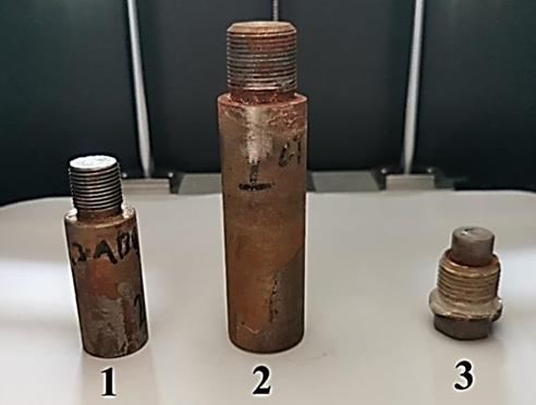
Fig. 1. General view of the steel protectors under study: 1 – factory-made steel protector (No. 1);
2 – self-made steel protector (No. 2); 3 – self-made steel protector (No. 3)
At the first stage, the operating potentials of the steel protectors (1-3) were measured using a standard silver chloride reference (SCR) electrode [7]. A second-class reference electrode with a ShP 4-2 plug manufactured in GOMEL was used as the standard SCR. This SCR is shown in Fig. 2.
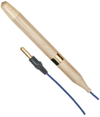
Fig. 2. Second-class reference electrode with ShP 4-2 plug manufactured by GOMEL (general view)
Control measurements were carried out using the authors’ cell for non-destructive testing of the electrochemical properties of marine protectors [6], whose design is shown in Fig. 3.
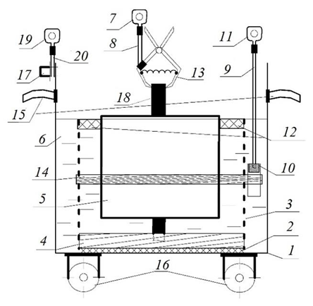
Fig. 3. Cell design for non-destructive testing of the electrochemical properties of marine protectors:
1 – steel tank; 2 – adhesive joint; 3 – perforated dielectric container; 4 – resilient dielectric gasket;
5 – replaceable test protector; 6 – seawater; 7, 11, 19 – measuring cable lug; 8, 9, 20 – measuring cable;
10 – reference electrode; 12 – dielectric float; 13 – spring-loaded self-clamping “crocodile” contact;
14 – rubber clamping ring; 15 – steel handles; 16 – wheels; 17 – bolted joint; 18 – steel fittings
The device was operated and the non-destructive inspection of individual ship protectors was performed as follows:
– an uncoated steel tank is filled with natural or artificial seawater to the specified mark;
– the test protector is placed vertically in the perforated dielectric container and fixed in position using the dielectric float;
– a measuring cable with a crimp lug is connected to the steel fitting of the protector using the clamping contact;
– 15 minutes after immersing the test protector in seawater, the potential difference (ΔU) between the protector and the reference electrode is measured with a millivoltmeter;
– after measuring the potential difference between the test protector and the reference electrode, the current in the measuring circuit formed by the protector under test, the ammeter, the uncoated steel tank and seawater is measured with an ammeter.
Figure 4 shows a general view of an automated device for non-destructive testing of the electrochemical properties of marine vessel protectors.
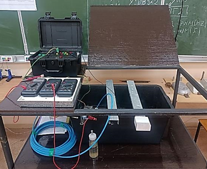
Fig. 4. Automated device for non-destructive testing of the technical condition of marine protectors (general view)
For each of the three protectors in the device shown in Fig. 4, 50 individual control measurements (a representative sample) of the potential of each steel protector (U1, U2, U3, mV) were taken at 1-minute intervals. The results were processed in MS Excel using standard methods of mathematical statistics. The following were calculated for statistical processing:
a) mathematical expectation (arithmetic mean); b) coefficient of variation; c) variance of the measurement results to assess the quality of the sample.
At the second stage, the protective current (I1, I2, I3, mA) was measured in the electrical circuits formed by the individual steel protector (anode), seawater, a stainless-steel cathode [6], and the measuring device. For each circuit, 50 individual current measurements (I, mA) were taken at 1-minute intervals.
Results and discussion
The results of the control measurements and their statistical processing are presented in the Table below.
Results of non-destructive testing of the technical condition of steel protectors
|
№ |
U1, mV |
U2, mV |
U3, mV |
I1, mA |
I2, mA |
I3, mA |
|
1 |
644 |
621 |
672 |
14 |
16 |
18 |
|
2 |
644 |
620 |
672 |
14 |
13 |
13 |
|
3 |
644 |
620 |
672 |
11 |
10 |
12 |
|
4 |
644 |
620 |
671 |
10 |
8 |
11 |
|
5 |
643 |
621 |
671 |
10 |
10 |
11 |
|
6 |
643 |
621 |
672 |
10 |
9 |
10 |
|
7 |
643 |
621 |
673 |
10 |
8 |
10 |
|
8 |
643 |
621 |
672 |
7 |
7 |
11 |
|
9 |
644 |
623 |
672 |
8 |
8 |
9 |
|
10 |
644 |
623 |
684 |
8 |
8 |
10 |
|
11 |
646 |
626 |
679 |
7 |
8 |
10 |
|
12 |
645 |
629 |
678 |
9 |
7 |
9 |
|
13 |
645 |
628 |
676 |
7 |
7 |
9 |
|
14 |
645 |
630 |
675 |
8 |
7 |
11 |
|
15 |
644 |
630 |
678 |
7 |
7 |
10 |
|
16 |
644 |
630 |
674 |
8 |
8 |
11 |
|
17 |
646 |
629 |
671 |
7 |
7 |
9 |
|
18 |
647 |
629 |
668 |
8 |
7 |
9 |
|
19 |
642 |
628 |
674 |
9 |
8 |
11 |
|
20 |
646 |
629 |
676 |
8 |
7 |
11 |
|
21 |
646 |
629 |
680 |
9 |
9 |
8 |
|
22 |
645 |
630 |
689 |
9 |
10 |
9 |
|
23 |
645 |
630 |
662 |
8 |
8 |
8 |
|
24 |
645 |
631 |
669 |
7 |
7 |
9 |
|
25 |
645 |
632 |
675 |
8 |
7 |
8 |
|
26 |
642 |
632 |
676 |
7 |
7 |
10 |
|
27 |
642 |
633 |
678 |
7 |
6 |
8 |
|
28 |
642 |
633 |
679 |
8 |
7 |
10 |
|
29 |
642 |
634 |
679 |
7 |
7 |
8 |
|
30 |
642 |
633 |
680 |
6 |
7 |
10 |
|
31 |
642 |
636 |
680 |
11 |
7 |
12 |
|
32 |
642 |
635 |
681 |
10 |
10 |
10 |
|
33 |
643 |
636 |
683 |
9 |
9 |
10 |
|
34 |
643 |
636 |
683 |
8 |
9 |
8 |
|
35 |
647 |
636 |
682 |
10 |
7 |
9 |
|
36 |
647 |
637 |
682 |
8 |
9 |
9 |
|
37 |
649 |
637 |
682 |
8 |
8 |
9 |
|
38 |
649 |
636 |
680 |
9 |
7 |
7 |
|
39 |
649 |
636 |
681 |
9 |
7 |
9 |
|
40 |
649 |
637 |
681 |
10 |
7 |
9 |
|
41 |
649 |
637 |
682 |
10 |
8 |
8 |
|
42 |
650 |
637 |
683 |
9 |
7 |
7 |
|
43 |
650 |
637 |
684 |
8 |
8 |
10 |
|
44 |
647 |
638 |
683 |
8 |
7 |
8 |
|
45 |
647 |
637 |
683 |
8 |
8 |
10 |
|
46 |
646 |
637 |
688 |
7 |
8 |
8 |
|
47 |
645 |
637 |
689 |
9 |
9 |
8 |
|
48 |
644 |
638 |
685 |
8 |
7 |
10 |
|
49 |
642 |
638 |
682 |
7 |
7 |
8 |
|
50 |
647 |
638 |
684 |
8 |
8 |
9 |
|
Mean |
644.98 |
631.04 |
678.10 |
8.60 |
8.04 |
9.62 |
|
Range |
8.00 |
18.00 |
27.00 |
8.00 |
10.00 |
11.00 |
|
Standard deviation |
1.90 |
5.04 |
4.77 |
1.22 |
1.06 |
1.24 |
|
Variance |
5.46 |
35.36 |
32.73 |
2.56 |
2.76 |
3.12 |
|
Standard deviation |
2.36 |
6.01 |
5.78 |
1.62 |
1.68 |
1.78 |
|
Coefficient of variation |
0.37 |
0.95 |
0.85 |
18.79 |
20.87 |
18.53 |
From the results shown in the Tables, the following can be concluded:
– the control measurements of protector potentials for all specimens are classified as precise based on the coefficient of variation Kvar 1-3 < 1% [8];
– the expected higher quality of the factory-made protector No. 1 is confirmed by its lower standard deviation for both U and I parameters. The standard deviation for specimen No. 1 is 2.5× lower for U parameter (relative to specimen No. 2) and 1.1× lower for I (relative to specimen No. 3);
– steel protectors manufactured by a ship’s mechanical service can be used on sea-going vessels after control tests, since their inspection results satisfy the requirements of the normative document [1].
The mean potential parameters of steel protectors No. 2 and 3 (workshop-made) lie within the same intervals as those of the factory protector No. 1:
│U1avg – U2avg│= 13.94 < 50 mV;
│U1avg – U3avg│= 33.14 < 50 mV
at R1-3 < 30 mV.
Conclusion
The following conclusions can be drawn from the completed study:
1. Sea-going vessels should implement incoming non-destructive testing of the technical condition of steel protectors, both for products manufactured at specialized facilities and for protectors made by shipowners’ mechanical services or by ship-repair specialists.
2. Implementing the incoming testing method will allow for an objective justification for the use of steel protectors, including those manufactured in-house.
3. The manufacturing quality of the factory-made steel protector is higher than that of the workshop-made items; however, for all specimens the coefficient of variation over 50 measurements is below 25%: the maximum values are 0.95% for U and 20.87% for I (specimen No. 2).
4. The use of incoming testing of steel protectors requires the development of automated measuring systems to minimize measurement errors and reduce the impact of the human factor on the part of ship crews.
1. РД 31.28.10-97. Комплексные методы защиты судовых конструкций от коррозии. М.: Изд-во ЦНИИМФ, 1997. 169 с.
2. ГОСТ 9.056-75. Стальные корпуса кораблей и судов. Общие требования к электрохимической защите. М.: Изд-во стандартов, 1986. 20 с.
3. ГОСТ 26501-85. Корпуса морских судов. Общие требования к электрохимической защите. М.: Изд-во стандартов, 1985. 7 с.
4. РЗК-НК-01. Руководство по защите корпусов надводных кораблей ВМФ от коррозии и обрастания. М.: Воен. изд-во, 2001. 258 с.
5. Чендлер К. А. Коррозия судов и морских сооружений / пер. с англ. И. А. Бархатова, В. И. Лемкова. Л.: Судостроение, 1988. 320 с.
6. Пат. 215562 U1 Рос. Федерация. Ячейка для неразрушающего контроля электрохимических свойств протек-торов морских судов / Ястребов Д. П., Рогожников А. О., Новосадов Б. И., Крутень Ю. В. № 2023109231; заявл. 11.04.2023; опубл. 05.12.2023.
7. ГОСТ 17792-72. Электрод сравнения хлорсеребряный насыщенный образцовый 2-го разряда. М.: Изд-во стандартов, 1972. 9 с.
8. Смагунова А. Н., Карпукова О. М. Методы математической статистики в аналитической химии: учеб. пособие. Иркутск: Изд-во ИГУ, 2008. 339 с.
