Россия
К объектам морской инфраструктуры относят различные системы и сооружения, которые необходимы для обеспечения функционирования морского транспорта и выполнения других видов обязательный операций на водном пространстве: пассажирские и грузовые терминалы, перевалочные комплексы, складские помещения, объекты инфраструктуры по поддержанию судов в работоспособном состоянии, системы теплоснабжения, газоснабжения, водоснабжения и системы электроснабжения, необходимые для непрерывного обеспечения различных процессов жизнедеятельности порта. Рассматривается вопрос эксплуатации разработанной экспериментальной конструкции ветроэнергетической установки (ВЭУ), утилизирующей вторичные энергетические ресурсы энергообъектов морской инфраструктуры, при ее размещении на дымовые трубы котельных установок портовых хозяйств. Проводится разработка экспериментальной ВЭУ, которая будет использовать вторичные энергетические ресурсы предприятия. Таким ресурсом в портовых хозяйствах могут быть уходящие газы котельной или мини-ТЭЦ на базе двигателей внутреннего сгорания и др., тепло которых будет утилизироваться в предлагаемой ВЭУ для генерации электроэнергии для покрытия части нужд энергообъекта. Внедрение ветроэнергетических установок в портовых хозяйствах представляет собой важную стратегическую инициативу с множеством преимуществ: энергонезависимость и снижение затрат на энергоснабжение; устранение резких колебаний цен на электроэнергию, которые могут быть вызваны изменениями в ценах на традиционные энергоносители; снижение выбросов парниковых газов; улучшение портами своего общественного имиджа, стимулирование экономического развития региона. Отмечено, что некоторые правительства и международные организации предлагают финансовую поддержку и стимулирующие меры для проектов по внедрению возобновляемых источников энергии; ВЭУ могут действовать как резервный источник энергии, обеспечивая более высокую надежность энергоснабжения в случае перебоев в основной сети и т. д. Все указанные мероприятия по размещению ВЭУ на дымовые трубы энергообъектов морской инфраструктуры дают возможность повысить эффективность выработки энергии от генерирующей установки в порту.
возобновляемые источники энергии, вторичные энергетические ресурсы, портовое хозяйство, ветроэнергетическая установка, интенсификация теплоотдачи, дымовые трубы энергообъектов
Introduction
The development of renewable energy sources (RES) is an integral step in the conservation of natural resources and plays a role in the decarbonization of enterprises of the fuel and energy complex, including energy facilities of the marine infrastructure [1, 2]. The paper considers the issue of developing an experimental wind turbine using heat transfer intensifiers in the form of blade swirlers [3] to generate electrical energy that can be used to cover their own needs of energy facilities of marine infrastructure, which include boiler houses or mini-CHP plants based on gas piston installations, on the chimneys of which can be installed developed by the authors of the wind turbine. Thermal energy from secondary energy resources is used in wind turbines to form rising swirling flows. In the developed design of the wind turbine, due to the hot surface of the chimney, the air around the pipe itself is heated, which subsequently rises up, twists with the help of swirlers, thereby creating an intensified flow. The energy of such a stream can be used to generate electricity, which will cover the own needs of the marine infrastructure facility. This will reduce the consumption of fuel and energy resources and reduce the anthropogenic impact on the environment.
Relevance of the study
The use of RES in port facilities is becoming increasingly relevant and important for several reasons:
– international and national environmental requirements are becoming increasingly strict, for example, the International Maritime Organization (IMO) is introducing new rules to reduce carbon emissions and other pollutants;
– despite high initial investments, operating costs when using renewable energy installations are often lower, due to low or zero fuel costs and minimal maintenance;
– ports implementing RES contribute to sustainable development and attract the attention of companies and partners interested in environmentally friendly initiatives;
– using the potential of RES will enable ports to reduce dependence on traditional hydrocarbon fuels and on their suppliers and, thereby, increase sustainable development regardless of fuel prices;
– the introduction of RES in port facilities stimulates the development of new technologies and innovations;
– there are already successful examples of using RES in ports around the world, for example, the Port of Rotterdam is actively investing in solar and wind farms, as well as in hydrogen fuel projects.
In general, the use of RES in port facilities is a step towards a sustainable future that will bring economic, environmental and social benefits.
Main part
In the literature, there are ways to locate wind turbines with a vertical axis of rotation in high places, for example, the uppermost support of a chimney [4]. Here, the chimney is considered only as a high point of placement of wind turbines. In this case, we are not talking about using the potential of flue gases. This placement option assumes a height of about 20 m, where the wind speed is 6-7% higher than at ground level. Such options lead to an increase in energy generation by an average of 18-21%.
The authors have developed an experimental wind power plant using heat transfer intensifiers in the form of blade swirlers [5]. A general view of an experimental wind turbine with tangential upstream diversion is shown in Fig. 1.
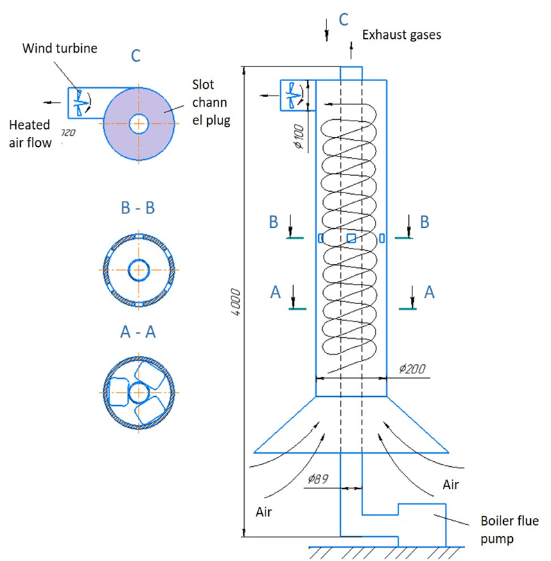
Fig. 1. General view of the experimental wind turbine with a tangential branch:
A-A – layout of the blade swirlers; B-B – layout of the holes in the casing for additional air inflow;
С – layout of the plug installation at the exit of heated air flows from the slot gap
The use of a method of twisting flows in wind power plays an important role due to the characteristics of such flows. They are concentrated in a stream (jet) of kinetic energy. The use of wind turbines [6], which, among other things, are capable of using low-potential air flows, are able to utilize heat flows, for example, when disposing of the heat of exhaust gases from a boiler house of a port facility, is very important. Such wind turbines are able to concentrate and usefully use energy on air flows that move even at low speeds, for example, from 3-4 m/s.
In the wind turbine proposed by the authors, which will be located in the upper part of the pipe, a tangential outlet of the rising warm air is performed. Such an installation is equipped with a casing, which is preferably made of composite materials to make the structure easier. In the described variant, the chimney is no longer considered as a high fulcrum, but as an object of thermal energy from the flue gases of an energy facility. During the operation of boiler houses, exhaust gases with a temperature not lower than the dew point are emitted into the chimney, the average value of which is not lower than 120 °C. The surface of the pipe, heated by the outgoing gases, gives off heat to the air near the wall, that is, it is heated in the slit space formed by the pipe and casing. The use of a powder allows you to concentrate the entire volume of air masses in a limited space, preventing it from dissipating. The heated air, as a result of the lifting forces acting on it, rushes upwards, passing through the vortices and is removed through the tangential outlet and, thereby, spins the blades of the wind power plant (Fig. 1, view С), which allows generating electric energy. To intensify the movement and increase the mass flow rate of air sucked into the lower slit channel, the design provides a confuser at the bottom of the casing, blade swirlers (Fig.1, type A-A), and holes are made along the height of the casing (Fig. 1, type B-B) necessary to ensure the inflow additional air. At the exit from the inter-tube space, the heated air, resting against the plug of the inter-tube space, enters the tangential outlet, which allows the entire volume of air to be concentrated on the blades of the generating device. All this will contribute to an increase in air flow through the slit channel and increase the flow rate at the outlet.
The installed blades for flow swirl have proven their efficiency in laboratory conditions during experiments [2]. Further research and design improvements will allow this technology to be adapted for wider application and integration into the energy system. A total of four levels of swirlers were installed uniformly along the height of the pipe (Fig. 2). Among other things, such blades stabilize the flow, which will lead to an improvement in the performance of wind turbines. The entire installation, enclosed in a casing, is shown in Fig. 3.
During the experiments, measurements were taken of the velocity of the wind turbine leaving the tangential outlet on the chimney without installed swirlers depending on the pipe wall temperature with closed openings (Fig. 1, view B-B). The results of the measurements are shown in Table 1. In the Table 2 shows the results of measurements of the velocity of the outgoing flow from the tangential outlet in the case of installing a galvanized sheet casing on the chimney. Four tiers of blade swirlers were installed with all the holes closed in the casing itself (Fig. 1, view B-B). The date of measurements at the experimental installation was 03/06/2024 (the ambient temperature was minus 1 °C, the wind speed was 3 m/s).
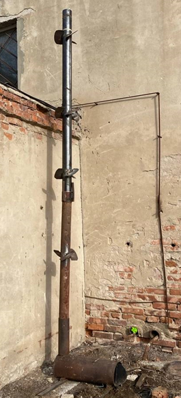
Fig. 2. Chimney with installed vane swirlers
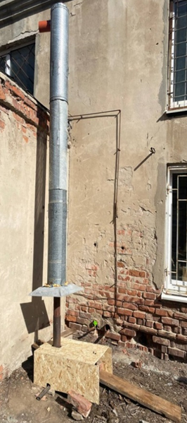
Fig. 3. Experimental setup with a casing installed
to create a slit channel
Table 1
Results of measurements of the velocity of ascending flows in the experimental setup
without installed vane swirlers
|
Pipe wall temperature, °С |
Flow rate, m/s |
Average air temperature in the intertube space, °С |
|
50 |
0.6-0.7 |
17.0 |
|
60 |
0.6-0.7 |
17.5 |
|
90 |
0.8-0.9 |
19.5 |
|
120 |
1.1-1.3 |
21.5 |
|
150 |
1.4-1.6 |
22.0 |
Table 2
Results of measurements of the velocity of ascending flows in the experimental setup
with installed blade swirlers, according to Fig. 2
|
Pipe wall temperature, °С |
Flow rate, m/s |
Average air temperature in the intertube space, °С |
|
30 |
3.2 |
27 |
|
60 |
3.6 |
34.8 |
|
90 |
4 |
36.2 |
|
120 |
5.4 |
45 |
|
150 |
5.5 |
60 |
|
180 |
6 |
64 |
From the above measurement data, it can be seen that with an increase in the value of the chimney wall temperature, the average temperature of the updraft in the wind turbine also increases. The measurements performed before and after the installation of the swirlers showed that this solution actually increases the exit velocity from the tangential outlet of the rising swirling air flows quite well. This shows the expediency and necessity of using swirlers for this kind of wind turbines.
From the tables based on the results of experimental measurements without vortices and with them, it can be seen that in the second case, the flow velocity through the tangential outlet increases by more than 3 times, which indicates the need and expediency of their use. The experiments performed with open holes (Fig. 1, view B-B) gave the opposite result – a decrease in the air flow velocity, as assumed, due to the dispersion of the mass of the swirling flow.
In the experimental wind turbine, the diameter of the wind wheel, which is supposed to be installed in the tangential branch, is 0.1 m (Fig. 1, view C). Let us plot the dependence of the electric power of the wind turbine generator Pwpp, W, on the flow velocity, m/s, leaving the tangential branch of the installation. The results are shown in Fig. 4.
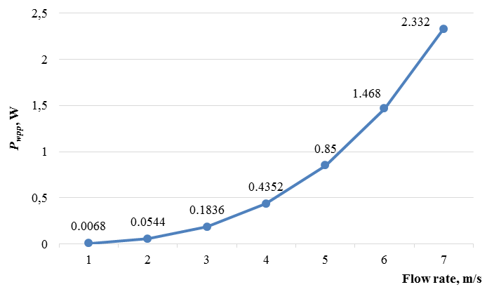
Fig. 4. The value of the generated power of the wind turbine from the flow speed of the vortex air flow
The power of the wind turbine on the chimney at a speed of 7 m/s is 2.3 W. Calculations show that an increase in the flow rate to 9 m/s and a diameter of D = 1.0 m, the power of wind turbines on chimneys can reach 499 W and will be quite sufficient to cover part of the own needs of the boiler house located in the port facility. In the future, the data obtained will be refined during experiments using direct current generators and contactless frequency meters. In the future, it is necessary to work out the issues of optimal geometric proportions of the size of the chimney and casing, as well as to conduct studies of changes in the temperature of flue gases at the outlet of the pipe to analyze the issue of reducing the temperature of the exhaust gases below the dew point, which can lead to a negative impact on corrosion processes in the pipe itself. In addition, the issues of determining the main technical and economic performance indicators of the created wind turbine will be analyzed.
Thus, the intensification of the movement of air flow in the slit gap between the pipe and the casing is a promising direction in the field of wind energy, which opens up new opportunities to increase the efficiency and adaptability of wind power plants for use in any industry, including for energy facilities of port facilities. Nevertheless, current developments still require significant attention to the issues of stability and reliability of structures, especially in conditions of various weather conditions. Further research is needed to optimize the parameters of such systems and their adaptation to various climatic conditions. In the long term, the successful implementation of such wind turbines in the wind energy sector can significantly increase the availability and prevalence of RES, contributing to a global transition to a sustainable and environmentally friendly energy future.
Conclusion
The method of placing wind turbines in the upper part of the pipes of power facilities of port facilities, considered by the authors, will contribute to the generation of electricity without reference to the speed and direction of ambient air, since the operation of such a wind turbine is based on the laws of heat transfer, namely on the phenomenon of free convection. It, in turn, occurs when the heat of the flue gases of a boiler house or mini-CHP based on internal combustion engines is utilized, and not when installing wind turbines at high points of artificial heights to use a faster wind flow of air. The introduction and operation of such installations will make it possible to partially compensate for the energy consumption of the enterprise for its own needs.
1. О морских портах в Российской Федерации и о внесении изменений в отдельные законодательные акты Российской Федерации: Федеральный закон РФ от 08.11.2007 № 261-ФЗ (ред. от 25.06.2012). URL: https://normativ.kontur.ru/document?moduleId=1&documentId=465471&ysclid=m2n76chgox547038986 (дата обращения: 02.09.2024).
2. Ильин Р. А., Шишкин Н. Д. Разработка ветроэнергетической установки для размещения на дымовые трубы энергообъектов морской инфраструктуры // Вестн. Астрахан. гос. техн. ун-та. Сер.: Морская техника и технология. 2020. № 2. С. 62–68.
3. Бирюк В. В., Горяинов С. Б., Угланов Д. А. Вихревая энергетика // Соврем. наука. 2011. № 2 (7). С. 220–225.
4. Пат. RU 2510611. Способ размещения роторной ветроэнергетической установки на дымовой трубе / Голощапов В. М., Баклин А. А., Терехин Е. А., Вострокнутов Е. В.; заявл. 03.08.2011; опубл. 10.04.2014.
5. Пат. RU 227702U1. Ветроэнергетическая установка / Ильин Р. А., Шишкин Н. Д., Гагиев И. Р.; заявл. 02.05.2024; опубл. 30.07.2024.
6. Серебряков Р. А. Ветроустановка с вихревым преобразователем потоков сплошной среды // Актуал. проблемы гуманитар. и естеств. наук. 2016. № 3 (86). С. 43–55.

