


Россия
Россия
Россия
Россия
Россия
Мировая статистика аварийности флота свидетельствует о том, что наиболее опасным видом повреждений инженерных конструкций являются хрупкие разрушения, которые возникают внезапно и распространяются с большой скоростью. Причинами хрупких разрушений являются дефекты типа коррозионно-усталостных трещин, часто возникающих по причине активных коррозионных процессов. В морской воде содержится большое количество микроорганизмов, способствующих ускорению коррозии и обрастанию соприкасающихся с водой металлоконструкций. Основным методом защиты от коррозии систем и механизмов морских рыбопромысловых судов является протекторная защита. Для повышения эффективности протекторной защиты необходимо совершенствовать методы технического диагностирования протекторов с целью использования новых методов на судоремонтных заводах и морских судах. Для технического диагностирования протекторов морских судов предлагается использовать контрольные электроды, выполненные из нержавеющей стали. Выполнены лабораторные испытания электрода из нержавеющей стали и стандартного хлорсеребряного электрода сравнения. Эксперимент проходил на установке для технического диагностирования протекторов морских судов, которая была специально разработана на кафедре «Энергетические установки и электро-оборудование судов» ФГБОУ ВО «Камчатский государственный технический университет». Контрольные измерения потенциала рабочего протектора выполняли в течение пяти дней, при этом ежедневно выполняли по 50 единичных контрольных измерений рабочего потенциала протектора с помощью каждого электрода. Точность результатов измерений оценивали с помощью математико-статистического метода. Результаты диа-гностирования потенциала протектора, полученные с помощью электрода, изготовленного из нержавеющей стали, соответствуют нормативным требованиям. Предлагаемый тип электрода может быть использован эки-пажами судов при техническом диагностировании протекторов морских судов.
защита судов, протекторная защита от коррозии, рабочий потенциал протекторов, техническое диагностирование протекторов, измерения рабочего потенциала протектора, стандартный электрод сравнения, нестандартный электрод сравнения
Introduction
The corrosion studies carried out by the authors [1, 2] on Kamchatkaꞌs sea-going vessels, have brought to light many cases of using low-quality protectors at these vessels. For this reason, the workers of small ship-repair enterprises of the Kamchatka Region applied to Kamchatka State Technical University with a request to develop a simple method for technical diagnostics of ship protectors in order to check their working capacity.
According to the standard requirements [3], when technically diagnosing ship protectors it is necessary to measure their operating potential and current output. These tread characteristics are assessed using an expensive set of devices [3]. It should be noted that standard methods [1, 4-10] of protector quality control are not intended for continuous non-destructive testing of individual marine protectors. It is also necessary to take into account the experience of using silver-chloride reference electrodes (CRE) on Kamchatkaꞌs sea-going vessels to measure the operating potential of protectors. No shipꞌs crew of Kamchatka fleet uses CRE in their practical work [11]. This is because of the high cost of CRE and the complexity of its storage. For this reason, it is necessary to stop using CRE when organizing incoming quality control of marine protectors and replace it with a non-standard control electrode intended for use at small ship repair enterprises and sea-going vessels.
The papers [12-17] present the results of tests of non-standard control electrodes (of aluminum, copper; electrodes made of shipꞌs hull steel, etc.) used to control the tread protection systems of sea-going vessels’ hulls. This paper presents the results of technical diagnostics of protectors using a control electrode made of stainless steel.
The purpose of the article is to exchange experience in the quality control of marine protectors.
Еxperimental part
For five days (from 11.14.2022 to 11.18.2022), the operating potential of a P-SSA-4 type protector made of AP-1 aluminum alloy was measured in the laboratory conditions. The measurements were performed using a UNI-T UT39E+ multimeter and two electrodes:
– CRE;
– a control electrode made of CR (chrome) 17 stainless steel in accordance with the recommendations of the regulatory document [3].
Fifty single measurements of the tread potential were carried out daily using each control electrode. The total time for carrying out daily measurements is approximately 10 minutes. A diagram of the installation for technical diagnostics of sea-going vessel protectors is shown in Fig. 1. This installation was developed at the department “Power Plants and Electrical Equipment of Ships” of the Federal State Budgetary Educational Institution of Higher Education “Kamchatka State Technical University”. The installation contains a steel container 1 filled with sea water 6. In the center of the steel container, there is a dielectric perforated container 3, which is attached to the steel container 1 using an adhesive connection 2. At the bottom of the perforated container 3, there is an elastic dielectric lining 4 made from foam-rubber. The perforated dielectric container 3 contains a replaceable controlled protector 5 fixed in the vertical position with the help of a float 12 made of dielectric material. A measuring cable 8 is connected to the steel armature 15 of the controlled protector through a spring-loaded self-clamping contact (of crocodile type) 13. A cable tip 7 is soldered to the free end of the measuring cable 8. A measuring cable 9 is soldered to the control electrode 10, besides the soldering point is protected with VK-9 glue. A cable tip 11 is soldered to the free end of the measuring cable 9 of the control electrode 10. The control electrode 10 is attached to the perforated container with the help of a rubber clamping ring 14.
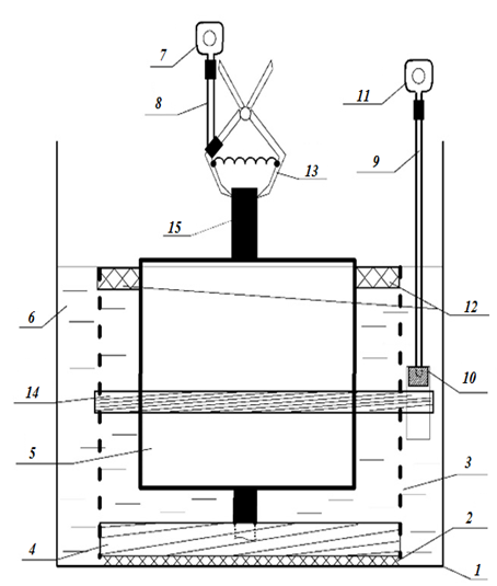
Fig. 1. The design of an installation for technical
diagnostics of marine vessel protectors
The experiment has been performed the following way:
– the steel container was filled with sea water to the specified level;
– the controlled protector was placed in the perforated dielectric container in the vertical position which was fixed with the help of a dielectric float;
– the measuring cable equipped with a cable tip was connected to the steel armature of the protector with the help of a self-clamping contact;
– the electrode was placed in seawater, and attached to a perforated container with the help of a rubber clamping ring;
– 5 minutes after placing the controlled protector in sea water, the potential difference (ΔU) between the protector and the reference electrode was measured, 50 control measurements being performed with a pause of about 5 seconds between measurements, according to the recommendations [18-22];
– the obtained measurement results were entered into special forms, the experimental data were digitized, and initial mathematical processing of the measurement results was carried out with the help of the Microsoft Office Excel 365 software product;
– after processing the measurement results, electrode No. 1 was removed from the electrical measuring circuit, and electrode No. 2 was attached;
– then the measurement cycle was repeated with the help of control electrode No. 2, according to the recommendations proposed in papers [18-22].
It is worth noting that in order to connect the electrode test wire to an electrical measuring instrument (multimeter), one can use a bolted connection, a built-up connection, or a simple cable tip. The UNI-T UT39E+ multimeter was used in the experiment, but other electrical measuring instruments can also be used.
Results of the experiment and discussion
The results of the experiment and assessment of their metrological characteristics with the help of mathematical and statistical methods [23], obtained on the above installation by means of two control electrodes, are given in the Table (Uav – simple average, mV; R – variation range; d – average linear deviation; D – dispersion; σ – average quadratic deviation; Kd – linear variation coefficient, %; Kr – oscillation coefficient, %; V – variation coefficient, %) and in Fig. 2, 3.
Results of monitoring the working potential of P-KOA-4 protector from 11/14/2022 to 11/18/2022
|
No.
|
Results of measurements of the potential difference between the protector |
|||||||||
|
Electrode No. 1 CRE |
Electrode No. 2 made from stainless steel |
|||||||||
|
14/11/2022 |
15/11/2022 |
16/11/2022 |
17/11/2022 |
18/11/2022 |
14/11/2022 |
15/11/2022 |
16/11/2022 |
17/11/2022 |
18/11/2022 |
|
|
1 |
939 |
945 |
941 |
933 |
947 |
393 |
390 |
383 |
375 |
388 |
|
2 |
939 |
946 |
942 |
933 |
948 |
393 |
390 |
383 |
374 |
388 |
|
3 |
939 |
945 |
942 |
933 |
948 |
393 |
390 |
383 |
375 |
388 |
|
4 |
939 |
946 |
941 |
932 |
948 |
393 |
390 |
382 |
374 |
388 |
|
5 |
939 |
945 |
942 |
932 |
947 |
393 |
390 |
383 |
375 |
388 |
|
6 |
939 |
946 |
941 |
932 |
948 |
393 |
390 |
382 |
374 |
387 |
|
7 |
939 |
945 |
942 |
932 |
948 |
393 |
390 |
382 |
375 |
387 |
|
8 |
939 |
946 |
942 |
932 |
947 |
393 |
390 |
383 |
374 |
387 |
|
9 |
939 |
946 |
942 |
932 |
948 |
393 |
390 |
383 |
375 |
388 |
|
10 |
939 |
946 |
942 |
932 |
948 |
394 |
390 |
383 |
374 |
388 |
|
11 |
939 |
946 |
942 |
932 |
947 |
394 |
390 |
383 |
375 |
388 |
|
12 |
939 |
946 |
942 |
932 |
948 |
394 |
390 |
383 |
374 |
388 |
|
13 |
939 |
946 |
942 |
932 |
948 |
394 |
390 |
383 |
375 |
388 |
|
14 |
939 |
946 |
942 |
932 |
948 |
394 |
390 |
383 |
374 |
388 |
|
15 |
939 |
946 |
942 |
932 |
948 |
394 |
390 |
383 |
375 |
387 |
|
16 |
940 |
946 |
942 |
932 |
948 |
394 |
390 |
383 |
374 |
387 |
|
17 |
939 |
946 |
942 |
932 |
948 |
394 |
390 |
383 |
375 |
387 |
|
18 |
940 |
946 |
942 |
932 |
948 |
394 |
390 |
383 |
374 |
388 |
|
19 |
939 |
946 |
942 |
932 |
948 |
394 |
390 |
383 |
375 |
388 |
|
20 |
939 |
946 |
942 |
932 |
948 |
394 |
390 |
383 |
374 |
388 |
|
21 |
940 |
946 |
942 |
932 |
948 |
394 |
391 |
383 |
375 |
388 |
|
22 |
939 |
946 |
942 |
932 |
948 |
394 |
391 |
383 |
374 |
388 |
|
23 |
939 |
946 |
942 |
932 |
948 |
394 |
391 |
383 |
375 |
388 |
|
24 |
940 |
946 |
942 |
932 |
948 |
394 |
391 |
383 |
374 |
388 |
|
25 |
939 |
946 |
942 |
932 |
948 |
394 |
391 |
383 |
375 |
388 |
|
26 |
939 |
946 |
942 |
932 |
948 |
394 |
391 |
383 |
374 |
388 |
|
27 |
939 |
946 |
942 |
932 |
948 |
394 |
391 |
383 |
375 |
388 |
|
28 |
940 |
946 |
942 |
932 |
948 |
394 |
391 |
383 |
374 |
388 |
|
29 |
939 |
946 |
942 |
932 |
948 |
394 |
391 |
383 |
375 |
388 |
|
30 |
940 |
946 |
943 |
932 |
948 |
394 |
391 |
383 |
375 |
388 |
|
31 |
940 |
946 |
942 |
932 |
948 |
394 |
391 |
383 |
374 |
388 |
|
32 |
939 |
946 |
942 |
932 |
948 |
394 |
391 |
383 |
375 |
388 |
|
33 |
940 |
946 |
942 |
932 |
948 |
394 |
391 |
383 |
374 |
388 |
|
34 |
939 |
946 |
942 |
932 |
948 |
394 |
391 |
383 |
375 |
388 |
|
35 |
940 |
946 |
942 |
932 |
948 |
394 |
391 |
383 |
374 |
388 |
|
36 |
939 |
946 |
942 |
932 |
948 |
394 |
391 |
383 |
375 |
388 |
|
37 |
940 |
946 |
942 |
932 |
948 |
394 |
391 |
383 |
374 |
388 |
|
38 |
939 |
946 |
942 |
932 |
948 |
394 |
391 |
383 |
375 |
388 |
|
39 |
940 |
946 |
942 |
932 |
948 |
394 |
391 |
383 |
374 |
388 |
|
40 |
939 |
946 |
942 |
932 |
948 |
394 |
391 |
383 |
375 |
388 |
|
41 |
940 |
946 |
942 |
932 |
948 |
394 |
391 |
383 |
374 |
388 |
|
42 |
939 |
946 |
942 |
932 |
948 |
394 |
391 |
383 |
375 |
388 |
|
43 |
940 |
946 |
942 |
932 |
948 |
394 |
391 |
383 |
374 |
388 |
|
44 |
939 |
946 |
942 |
932 |
948 |
394 |
391 |
383 |
375 |
388 |
|
45 |
940 |
946 |
942 |
932 |
948 |
394 |
391 |
383 |
374 |
388 |
|
46 |
939 |
946 |
942 |
932 |
948 |
394 |
391 |
383 |
375 |
388 |
|
47 |
940 |
946 |
942 |
932 |
948 |
394 |
391 |
383 |
374 |
388 |
|
48 |
940 |
946 |
942 |
932 |
948 |
394 |
391 |
383 |
375 |
388 |
|
49 |
940 |
946 |
942 |
932 |
948 |
394 |
391 |
383 |
374 |
388 |
|
50 |
939 |
946 |
942 |
932 |
948 |
394 |
391 |
383 |
375 |
388 |
|
Uav, mV |
939.34 |
945.92 |
941.96 |
932.06 |
947.92 |
393.82 |
390.60 |
382.94 |
374.52 |
387.88 |
|
R |
1.00 |
1.00 |
2.00 |
1.00 |
1.00 |
1.00 |
1.00 |
1.00 |
1.00 |
1.00 |
|
d |
0.45 |
0.15 |
0.12 |
0.11 |
0.15 |
0.30 |
0.48 |
0.11 |
0.50 |
0.21 |
|
D |
0.22 |
0.07 |
0.08 |
0.06 |
0.07 |
0.15 |
0.24 |
0.06 |
0.25 |
0.11 |
|
σ |
0.48 |
0.27 |
0.28 |
0.24 |
0.27 |
0.39 |
0.49 |
0.24 |
0.50 |
0.33 |
|
Kd, % |
0.05 |
0.02 |
0.01 |
0.01 |
0.02 |
0.07 |
0.12 |
0.03 |
0.13 |
0.05 |
|
Kr, % |
0.11 |
0.11 |
0.21 |
0.11 |
0.11 |
0.25 |
0.26 |
0.26 |
0.27 |
0.26 |
|
V, % |
0.05 |
0.03 |
0.03 |
0.03 |
0.03 |
0.10 |
0.13 |
0.06 |
0.13 |
0.08 |
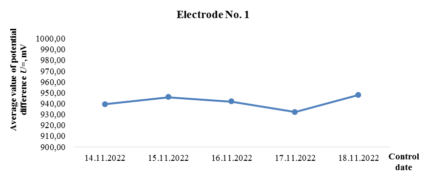
Fig. 2. Dynamics of the results of the potential difference measuring in the period
from November 14, 2022 to November 18, 2022, obtained with the help of electrode No. 1 (CRE)
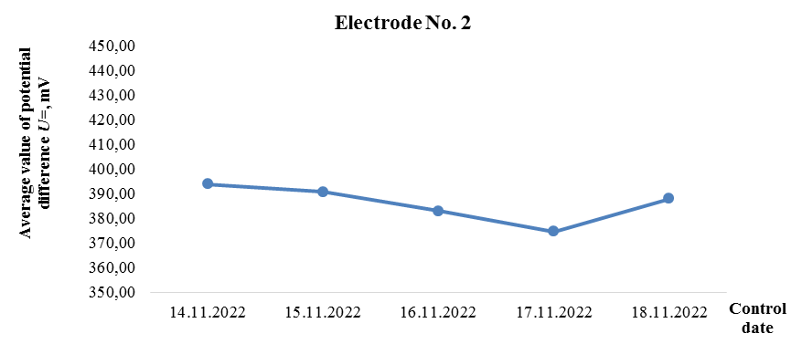
Fig. 3. Dynamics of the results of the potential difference measuring in the period
from November 14, 2022 to November 18, 2022, obtained with the help of electrode No. 2 made of stainless steel
The results of the experiment given in the Table show that each group of measurements is homogeneous, the degree of dispersion of the measurement results is insignificant, since V < 1%. The dynamics of changes in the results of the potentialꞌs measurements over the period of the experiment is illustrated in Fig. 2, 3.
The results of the experiment given in Fig. 2, 3, show the following:
– repeatability (convergence) of the control measurement results corresponds to the accuracy category of “precise measurements”, since the variation coefficient V, %, has proved to be less than 1% [23];
– intra-laboratory precisionness [24] of measurement results meets the requirement: |Xmax – Xmin| = |948 – 932| = 16 ≤ 20 mV [10].
The results of measuring the protectorꞌs working potential, obtained with the help of the control electrode made of stainless steel, have shown the following:
– repeatability (convergence) of the control measurement results, according to [23], corresponds to the accuracy category of “precise measurements”, since the variation coefficient V, %, has proved to be less than 1%;
– intra-laboratory precisionness [24] of measurement results complies with the condition: |Xmax – Xmin| = |394 – 374| = 20 ≤ 20 mV [10].
Conclusion
1. The results of monitoring the protectorꞌs potential obtained with the help of an electrode made of stainless steel, comply with standard requirements.
2. The results of the research can be used in training operators for technical diagnostics of sea-going vessels and shipsꞌ protectors.
1. Швецов В. А., Белов О. А., Белозеров П. А., Шунькин Д. В. Контроль систем протекторной защиты стальных судов и кораблей: моногр. Петропавловск-Камчатский: Изд-во КамчатГТУ, 2016. 109 с.
2. Ястребов Д. П., Белов О. А., Швецов В. А., Белавина О. А. О выборе электродов для контроля систем протек-торной защиты стальных судов и кораблей // Вестн. Астрахан. гос. техн. ун-та. Сер.: Морская техника и технология. 2019. № 4. С. 39-45.
3. ISO 15589-2-12. Petroleum, petrochemical and natural gas industries - Cathodic protection of pipeline transportation systems. URL: https://www.iso.org/standard/51992.html (дата обращения: 28.07.2023).
4. Зобочев Ю. Е., Солинская Э. В. Защита судов от коррозии и обрастания. М.: Транспорт, 1984. 174 с.
5. Коробцов И. М. Техническое обслуживание и ремонт флота. М.: Транспорт, 1975. 195 с.
6. РД 31.28.10-97. Комплексные методы защиты судовых конструкций от коррозии. М.: ЦНИИМФ, 1997. 169 с.
7. ГОСТ 9.056-75. Стальные корпуса кораблей и судов. Общие требования к электрохимической защите. М.: Изд-во стандартов, 1986. 20 с.
8. ГОСТ 26501-85. Корпуса морских судов. Общие требования к электрохимической защите. М.: Изд-во стан-дартов, 1985. 7 с.
9. Чендлер К. А. Коррозия судов и морских сооружений / пер. с англ. И. А. Бархатова, В. И. Лемкова. Л.: Судо-строение, 1988. 320 с.
10. РЗК-НК-01. Руководство по защите корпусов наводных кораблей ВМФ от коррозии и обрастания. М.: Воен. изд-во, 2001. 258 с.
11. Ястребов Д. П., Белов О. А., Швецов В. А., Ушакевич А. П., Кузнецов Г. В. О целесообразности использования хлорсеребряных электродов для контроля систем протекторной защиты стального корпуса судна // Техническая эксплуатация водного транспорта: проблемы и пути развития: материалы Междунар. науч.-практ. конф. (Петропавловск-Камчатский, 23-25 октября 2019 г.). Петропавловск-Камчатский: Изд-во КамчатГТУ, 2020. С. 121-124.
12. Ястребов Д. П., Шунькин Д. В., Рогожников А. О., Кузнецов Г. В. К вопросу использования цинковых электро-дов для контроля протекторной защиты судов и кораблей // Вестн. Астрахан. гос. техн. ун-та. Сер.: Морская техника и технология. 2021. № 2. С. 16-23.
13. Ястребов Д. П., Белов О. А., Швецов В. А., Белавина О. А., Зайцев С. А. К вопросу использования стальных пластин для контроля протекторной защиты корпусов судов и кораблей // Техническая эксплуатация водного транспор-та: проблемы и пути развития Материалы Междунар. науч.-практ. конф. (Петропавловск-Камчатский, 23-25 октября 2019 г.). Петропавловск-Камчатский: Изд-во КамчатГТУ, 2020. С. 125-129.
14. Ястребов Д. П., Белов О. А., Швецов В. А., Тарабанов Б. В., Зайцев С. А. К вопросу использования электродов из судокорпусной стали для контроля защищенности от коррозии корпусов судов и кораблей // Вестн. Астрахан. гос. техн. ун-та. Сер.: Морская техника и технология. 2020. № 2. С. 15-21.
15. Ястребов Д. П., Белов О. А., Швецов В. А., Ушакевич А. П., Кузнецов Г. В., Тарабанов Б. В. К вопросу ис-пользования алюминиевых электродов для контроля защищенности от коррозии стальных корпусов судов и кораблей // Вестн. Астрахан. гос. техн. ун-та. Сер.: Морская техника и технология. 2021. № 3. С. 23-32.
16. Ястребов Д. П. К вопросу использования медных электродов для контроля защищенности от коррозии сталь-ных корпусов судов и кораблей // Вестн. Астрахан. гос. техн. ун-та. Сер.: Морская техника и технология. 2021. № 4. С. 43-51.
17. Ястребов Д. П. К вопросу изготовления цинковых электродов сравнения для морских судов и кораблей // Вестн. Астрахан. гос. техн. ун-та. Сер.: Морская техника и технология. 2022. № 4. С. 38-46.
18. Белов О. А., Швецов В. А., Ястребов Д. П. Обоснование оптимальной периодичности контроля работы про-текторной защиты стальных корпусов судов // Эксплуатация мор. трансп. 2017. № 1 (82). С. 41-48.
19. Белов О. А., Швецов В. А., Ястребов Д. П., Белавина О. А., Шунькин Д. В. Внедрение усовершенствованного способа контроля систем протекторной защиты стальных корпусов судов Камчатского флота // Вестн. Камчат. гос. техн. ун-та. 2017. № 39. С. 6-11.
20. Швецов В. А., Белов О. А., Белавина О. А., Ястребов Д. П. Обоснование возможности исключения внешнего осмотра систем протекторной защиты стальных корпусов судов // Вестн. Астрахан. гос. техн. ун-та. Сер.: Морская тех-ника и технология. 2017. № 1. С. 29-38.
21. Белозеров П. А., Швецов В. А., Белавина О. А., Шунькин Д. В., Коростылев Д. В., Пахомов В. А., Малинов-ский С. А. Обоснование способа выбора контрольных точек для измерения защитного потенциала стальных корпусов кораблей и судов // Вестн. Камчат. гос. техн. ун-та. 2014. № 28. С. 6-11.
22. Швецов В. А., Белозеров П. А., Белавина О. А., Шунькин Д. В., Малиновский С. А. Обоснование выбора необ-ходимого числа параллельных измерений защитного потенциала стальных корпусов кораблей и судов в контрольной точке // Вестн. Камчат. гос. техн. ун-та. 2016. № 35. С. 40-46.
23. ГОСТ Р 8.736-2011. Государственная система обеспечения единства измерений (ГСИ). Измерения прямые мно-гократные. Методы обработки результатов измерений. Основные положения. URL: http://docs.cntd.ru/document/1200089016 (дата обращения: 28.07.2023).
24. Смагунова А. Н. Шмелева Е. И., Швецов В. А. Алгоритмы оперативного и статистического контроля качества работы аналитической лаборатории: метод. рук-во. Новосибирск: Наука, 2008. 60 с.
