


Russian Federation
Low-consumption turbomachines are devices that play an important role in the drive of various units in the field of shipbuilding, aircraft engineering and other branches of heavy engineering. They have some advantages over a high-average power turbine. The largest number of low-consumption turbomachines are made partial, i.e. with partial intake. The principle of a turbine with partial flapping of the impeller is considered as one of the types of partial turbomachines. The influence of the main velocity characteristic of the turbine stage on the loss of kinetic energy in the stage is investigated. The simulation of gas dynamic processes occurring in the turbine stage was carried out using the ANSYS Workbench software package. With the help of this complex, a three-dimensional geometric model of the turbine stage with varying degrees of impeller damping was created. By applying the finite element method, a computational grid, a computational model are generated, and boundary conditions of a numerical experiment are set. The result of the numerical experiment is graphs of the dependence of kinetic energy loss on the circumferential velocity (speed characteristics of the turbine stage). This dependence can be represented not only graphically, but also with the help of mathematical apparatus. An example of such an apparatus is the polynomial dependence. The considered mathematical design can be used in order to optimize mathematical models of gas flow in the flow part of a low-flow turbine. Cubic two-parameter polynomials of kinetic energy losses in the flow part of the nozzle and impeller are obtained, and an assessment of its applicability in the current mathematical model is given.
nozzle diaphragm, loss coefficient, runner, kinetic energy, numerical method, experiment, calculation grid, gas dynamics, low-consumption turbine
Introduction
The vast majority of low-consumption marine turbomachines are manufactured with partial intake – partial. This is due to a number of advantages compared to the use of small full-size underwater turbines. The paper considers the very principle of a turbine with partial blading of the runner (TPBR) without reference to the thermodynamic properties of the working fluid. Low-cost marine turbines that can be considered in this study, including steam turbines, gas turbines, have their advantages and limitations. For example, steam turbines have high efficiency and good reliability, but they require large dimensions and a long time to heat. Gas turbines, on the other hand, are compact and can quickly achieve operating parameters, but their efficiency may be lower, especially at low loads. Therefore, the choice of turbine type should be based on specific requirements and operating conditions [1-4].
The optimal choice will allow achieving high efficiency of utilization turbo generators, which will lead to a reduction in fuel consumption and material costs in marine engines [5]. The use of utilization turbogenerators in collaboration with internal combustion engines is one of the measures that can improve the efficiency of marine engines. This is an important step in the development of marine energy, which will help reduce the negative impact on the environment and ensure more efficient use of resources [6].
The main graphs characterizing the efficiency of turbine stages that are found in the scientific literature are graphs of the dependence of the efficiency coefficient on u1/C0. This parameter is the main speed characteristic of the stage. According to this parameter, the optimum point of kinetic energy losses, the velocity coefficient of the nozzle diaphragm and the runner are also fixed. Determining the optimal operating mode of the turbine stage while obtaining maximum efficiency with minimal kinetic energy losses is an urgent topic for research.
Goals and objectives of the study
The purpose of this study is to obtain polynomial dependences of energy losses in the flow part of the nozzle diaphragm and runner from the main speed characteristic of the u1/C0 stage.
Research objectives:
– based on previous numerical experiments conducted in this field [7-9]. The loss coefficients in the nozzle diaphragm and runner are determined;
– the method of mathematical approximation determines the polynomial dependences of kinetic energy losses on partiality and u1/C0;
– comparison of the values of the velocity coefficients of the nozzle diaphragm and runner obtained numerically with the result of the obtained mathematical dependencies.
The article [7] examines the study of models in which the velocity coefficients of nozzle diaphragm (ND) and runner (R) are determined based on experimental data. However, using a numerical experiment, it is possible to identify the distinctive features of the flow in these models and decide on the need for a semi-experimental study of the flow characteristics in ND and R using a simulation bench. Such a study was carried out in a scientific paper [8] on a simulation stand using the ANSYS CFX software. In Fig. 1 shows one of the stages of an inflow low-consumption TPBR.
The simulation of gas dynamic processes occurring in the turbine stage in the study was carried out using the ANSYS Workbench software package [9]. With the help of this complex, a three-dimensional model of the turbine stage with varying degrees of impeller damping was created. Using the finite element method, a computational grid was generated, a computational model was created, and boundary conditions for a numerical experiment were set.
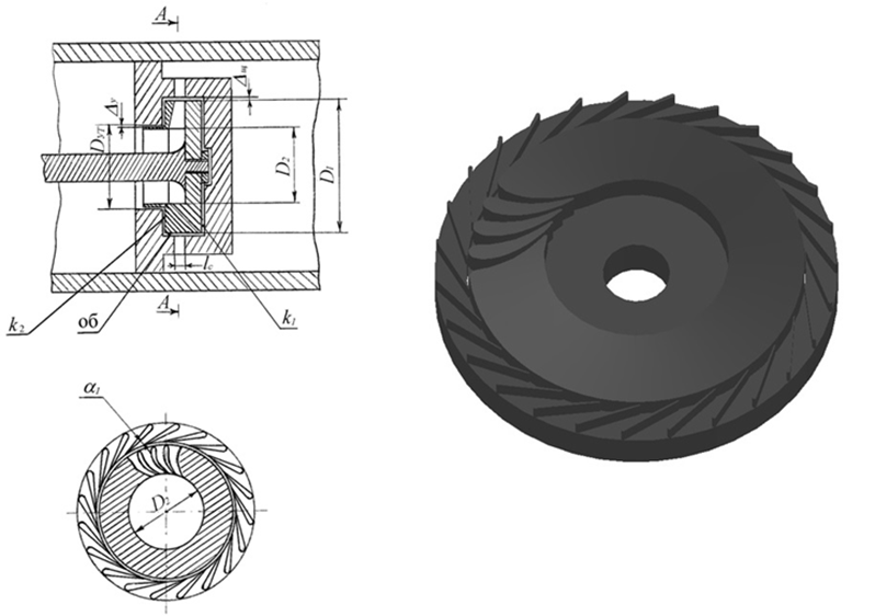
a b
Fig. 1. Diagram (a) and three-dimensional model (b) of a low-flow turbine stage
The results of the study
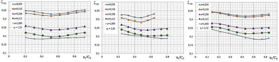
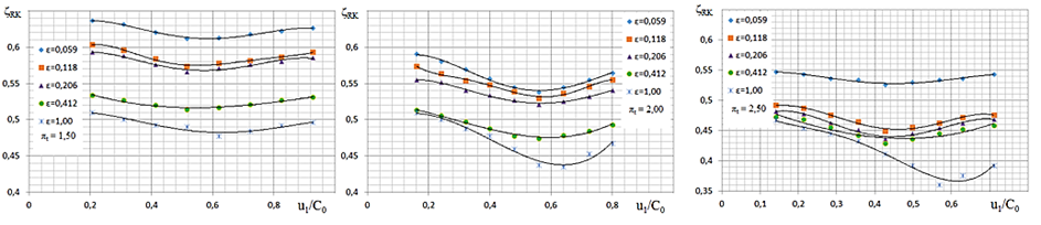
In [7], a TPBR was studied at various degrees of partial R. The values of the velocity coefficient ND and the velocity coefficient R were obtained. The velocity coefficients of ND and R with the energy loss coefficients in the flow part of ND and R have a certain interdependence expressed by the formulas [8]. Fig. 2 shows the dependences of the loss coefficients in the flow part of the ND for the stage in the range of ε from 0.059 to 1.00 and πt from 1.5 to 2.5 from u1/C0 [10, 11].
 a b c
a b c
Fig. 2. Two-dimensional dependence of the loss coefficient in the flow part of ND on u1/C0 with a degree
of partiality ε from 0.059 to 1.00: a – by πt = 1.5; b – by πt = 2.0; c – by πt = 2.5
The graphs of the dependence of the loss coefficient in the flow part of ND are a graphical representation of energy losses, which can be used to create polynomials expressing the dependence of ζND on the parameters u1/C0 and ε. The loss coefficient in ND can be expressed as a function of u1/C0 has the general form:
ζND(ε) = A(u1/C0)4 + B(u1/C0)3 + C(u1/C0)2 + D(u1/C0) + E.
For each degree of partiality in the range from 0.059 to 1.00, the polynomial has coefficients shown in Tables 1-3 [12].
Table 1
Coefficients of the nozzle diaphragm unit polynomial at the degree of expansion πt = 1.5
|
Degree of partiality ε |
Coefficients of the nozzle diaphragm unit polynomial |
||||
|
A |
B |
C |
D |
E |
|
|
0.059 |
–1.271 |
2.863 |
–2.086 |
0.541 |
0.302 |
|
0.188 |
–0.871 |
1.861 |
–1.233 |
0.265 |
0.316 |
|
0.206 |
–0.529 |
1.135 |
–0.682 |
0.067 |
0.265 |
|
0.412 |
–1.142 |
2.507 |
–1.729 |
0.384 |
0.193 |
|
1.000 |
0.477 |
–1.264 |
1.212 |
–0.477 |
0.247 |
Table 2
Coefficients of the nozzle diaphragm unit polynomial at the degree of expansion πt = 2.0
|
Degree of partiality ε |
Coefficients of the nozzle diaphragm unit polynomial |
||||
|
A |
B |
C |
D |
E |
|
|
0.059 |
–11.644 |
21.558 |
–14.025 |
3.741 |
0.025 |
|
0.188 |
–6.674 |
12.729 |
–8.203 |
2.064 |
0.131 |
|
0.206 |
–1.629 |
3.023 |
–1.683 |
0.202 |
0.281 |
|
0.412 |
–1.057 |
2.116 |
–1.259 |
0.137 |
0.253 |
|
1.000 |
1.211 |
–2.474 |
1.846 |
–0.647 |
0.295 |
Table 3
Coefficients of the nozzle diaphragm unit polynomial at the degree of expansion πt = 2.5
|
Degree of partiality ε |
Coefficients of the nozzle diaphragm unit polynomial |
||||
|
A |
B |
C |
D |
E |
|
|
0.059 |
–3.947 |
6.456 |
–3.446 |
0.635 |
0.306 |
|
0.188 |
–3.508 |
5.704 |
–2.952 |
0.482 |
0.318 |
|
0.206 |
–4.588 |
7.598 |
–4.192 |
0.813 |
0.227 |
|
0.412 |
–6.856 |
11.293 |
–6.243 |
1.238 |
0.175 |
|
1.000 |
4.748 |
–6.223 |
2.919 |
–0.736 |
0.304 |
A mathematical model that allows us to determine the loss coefficient in the flow part of the ND depending on two factors (ε and u1/C0) is presented in the form of a two-parameter dependence ζND = f(ε, u1/C0), for each πt.
With the degree of expansion πt = 1.5:
ζND(ε, M1t) = 0.205 – 0.062ε – 0.002(u1/C0) + 0.083ε2 – 0.0014ε(u1/C0) + 0.0077(u1/C0)2 – 0.03ε3 + 0.0013ε2(u1/C0) – 0.0022ε(u1/C0)2 – 0.0013(u1/C0)3.
With the degree of expansion πt = 2.0:
ζND(ε, M1t) = 0.213 – 0.035ε – 0.0015(u1/C0) + 0.071ε2 – 0.001ε(u1/C0) + 0.0063(u1/C0)2 – 0.03ε3 + 0.007ε2(u1/C0) – 0.003ε(u1/C0)2 – 0.0013(u1/C0)3.
With the degree of expansion πt = 2.5:
ζND(ε, M1t) = 0.228 – 0.47ε – 0.0016(u1/C0) + 0.063ε2 – 0.0066ε(u1/C0) + 0.0072(u1/C0)2 – 0.025ε3 + 0.001ε2(u1/C0) – 0.0048ε(u1/C0)2 – 0.0026(u1/C0)3.
A graphical representation of the two-parameter dependence ζND = f(ε, u1/C0), with πt = 1.5 is shown in Fig. 3.
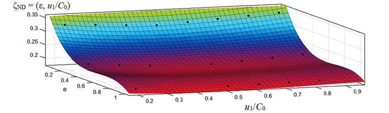
Fig. 3. Three-dimensional dependence of the loss coefficient in the flow part of the ND on u1/C0
and the degree of partiality ε, with πt = 1.5
This model makes it possible to more accurately estimate the value of ζND for various combinations of the values of ε and u1/C0. Similarly, the empirical dependences for the loss coefficient in the runner are determined (Fig. 4) [13].
a b c
Fig. 4. Two-dimensional dependence of the loss coefficient in the flow part of R on u1/C0 with a degree
of partiality ε from 0.059 to 1.00: a – by πt = 1.5; b – by πt = 2.0; c – by πt = 2.5
The loss coefficient in R can also be expressed as a function u1/C0 has the general form:
ΖR(ε) = A(u1/C0)4 + B(u1/C0)3 + C(u1/C0)2 + D(u1/C0) + E.
For each degree of partiality in the range from 0.059 to 1.00, the polynomial has coefficients shown in Tables 4-6.
Table 4
Coefficients of the runner unit polynomial at the degree of expansion πt = 1.5
|
Degree of partiality ε |
Coefficients of the runner unit polynomial |
||||
|
A |
B |
C |
D |
E |
|
|
0.059 |
–1.205 |
2.722 |
–2.000 |
0.509 |
0.595 |
|
0.188 |
–1.106 |
2.466 |
–1.741 |
0.393 |
0.577 |
|
0.206 |
–1.374 |
3.048 |
–2.194 |
0.546 |
0.550 |
|
0.412 |
–0.723 |
1.557 |
–1.029 |
0.200 |
0.524 |
|
1.000 |
–0.646 |
1.565 |
–1.182 |
0.271 |
0.491 |
Table 5
Coefficients of the runner unit polynomial at the degree of expansion πt = 2.0
|
Degree of partiality ε |
Coefficients of the runner unit polynomial |
||||
|
A |
B |
C |
D |
E |
|
|
0.059 |
1.735 |
–1.312 |
–0.047 |
0.054 |
0.5824 |
|
0.188 |
12.288 |
–20.268 |
12.125 |
–3.207 |
0.874 |
|
0.206 |
6.000 |
–9.947 |
6.122 |
–1.744 |
0.735 |
|
0.412 |
–1.092 |
3.139 |
–2.571 |
0.695 |
0.447 |
|
1.000 |
17.107 |
–28.445 |
16.933 |
–4.440 |
0.927 |
Table 6
Coefficients of the runner unit polynomial at the degree of expansion πt = 2.5
|
Degree of partiality ε |
Coefficients of the runner unit polynomial |
||||
|
A |
B |
C |
D |
E |
|
|
0.059 |
–2.714 |
4.583 |
–2.508 |
0.468 |
0.519 |
|
0.188 |
–6.135 |
10.859 |
–6.314 |
1.309 |
0.404 |
|
0.206 |
–8.315 |
14.135 |
–7.956 |
1.621 |
0.374 |
|
0.412 |
–8.478 |
14.357 |
–8.080 |
1.655 |
0.363 |
|
1.000 |
16.260 |
–23.339 |
11.425 |
–2.426 |
0.642 |
In general, the analysis of the dependence graphs presented in Fig. 4 shows the possibility of obtaining cubic two-parameter polynomials ζR = f(ε, u1/C0).
With the degree of expansion πt = 1.5:
ζR(ε, M1t) = 0.527 – 0.072ε – 0.001(u1/C0) + 0.026ε2 + 0.0017ε(u1/C0) + 0.0085(u1/C0)2 + 0.01ε3 – 0.002ε2(u1/C0) – 0.0002ε(u1/C0)2 – 0.0002(u1/C0)3.
With the degree of expansion πt = 2.0:
ζR(ε, M1t) = 0.495 – 0.077ε – 0.016(u1/C0) – 0.001ε2 – 0.001ε(u1/C0) + 0.004(u1/C0)2 + 0.018ε3 – 0.004ε2(u1/C0) – 0.0018ε(u1/C0)2 + 0.0035(u1/C0)3.
With the degree of expansion πt = 2.5:
ζR(ε, M1t) = 0.435 + 0.49ε – 0.018(u1/C0) + 0.104ε2 – 0.0067ε(u1/C0) + 0.0081(u1/C0)2 – 0.074ε3 – 0.004ε2(u1/C0) – 0.0038ε(u1/C0)2 + 0.053(u1/C0)3.
A graphical representation of the two-parameter dependence ζR = f(ε, u1/C0), with πt = 1.5 is shown in Fig. 5.
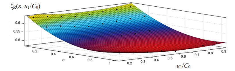
Fig. 5. Three-dimensional dependence of the loss coefficient in the flow part of the R on u1/C0
and the degree of partiality ε, with πt = 1.5
The adequacy of any mathematical model must be verified by a physical experiment. Due to the lack of results of a physical experiment on the energy loss coefficients in the flow part of the runner and nozzle diaphragm for the stage under study, the adequacy of the polynomial dependence can be performed using such an integral characteristic as efficiency.
When introducing the obtained energy loss dependencies into the existing mathematical model, the deviation of the internal efficiency between the calculated and the obtained input of the physical experiment is no more than 2.5%, which does not exceed the experimental error.
Conclusion
In the course of the study, the following tasks were completed and the relevant conclusions were obtained:
– based on previous studies, graphs of the dependence of energy losses in the flow part of ND and R on u1/C0 were constructed;
– using mathematical approximation methods, mathematical dependences of energy losses in were obtained for each degree of partiality ζND = f(ε, u1/C0) and ζR = f(ε, u1/C0);
– the obtained polynomial dependencies can be used to calculate the flow part from a turbine stage of this type and will allow modeling the parameters for further improvement.
1. Rakov G. L., Pautov D. V., Smirnov M. V., Kuklina N. I. O vozmozhnosti sozdaniia utilizatsionnykh turboge-neratorov s osesimmetrichnymi soplami dlia dvigatelei vnutrennego sgoraniia [On the possibility of creating utilization turbogenerators with axisymmetric nozzles for internal combustion engines]. Nauchno-tekhnicheskie vedomosti Sankt-Peter-burgskogo gosudarstvennogo politekhnicheskogo universiteta, 2015, no. 3 (226), pp. 7-16.
2. Chekhranov S. V., Simashov R. R., Khan'kovich I. N. Razvitie teploutilizatsionnykh tekhnologii v sudovoi ener-getike [Development of heat recovery technologies in marine power engineering]. Morskie intellektual'nye tekhnologii, 2017, no. 3-2 (37), pp. 107-111.
3. Erofeev V. L., Zhukov V. A., Mel'nik O. V. O vozmo-zhnostiakh ispol'zovaniia vtorichnykh energeticheskikh re-sursov v sudovykh DVS [On the possibilities of using secondary energy resources in marine internal combustion engines]. Vestnik Gosudarstvennogo universiteta morskogo i rechnogo flota imeni admirala S. O. Makarova, 2017, vol. 9, no. 3, pp. 570-580. DOI:https://doi.org/10.21821/2309-5180-2017-9-3-570-580.
4. Matveenko V. T., Ocheretianyi V. A., Dologlonian A. V. Kharakteristiki rabochikh protsessov vozdukhonezavisi-mykh odnokonturnykh mikrogazoturbinnykh ustanovok dlia podvodnoi tekhniki [Characteristics of the working processes of air-independent single-circuit micro-gas turbine installations for underwater equipment]. Vestnik Gosudarstvennogo universiteta morskogo i rechnogo flota imeni admirala S. O. Makarova, 2017, vol. 9, no. 3, pp. 612-618. DOI:https://doi.org/10.21821/2309-5180-2017-9-3-612-618.
5. Solov'ev A. V., Chirkova M. M., Popov N. F. Povyshenie effektivnosti sudovykh energeticheskikh ustanovok [Improving the efficiency of marine power plants]. Vestnik Astrakhanskogo gosudarstvennogo tekhnicheskogo univer-siteta. Seriia: Morskaia tekhnika i tekhnologiia, 2018, no. 4, pp. 101-106. DOI:https://doi.org/10.24143/2073-1574-2018-4-101-106.
6. Abul K. A. Otsenka vozmozhnostei utilizatsionnykh ustanovok glavnykh dvigatelei krupnotonnazhnykh sudov transportnogo flota [Assessment of the possibilities of recycling installations of the main engines of large-tonnage vessels of the transport fleet]. Vestnik Astrakhanskogo gosudarstvennogo tekhnicheskogo universiteta. Seriia: Morskaia tekhnika i tekhnologiia, 2009, no. 1, pp. 121-125.
7. Kriukov A. A., Chekhranov S. V. Sravnenie znachenii koeffitsientov skorosti v turbinnoi stupeni s chastichnym oblopachivaniem rabochego kolesa [Comparison of the values of the speed coefficients in the turbine stage with partial flapping of the impeller]. Vestnik Gosudarstvennogo universiteta morskogo i rechnogo flota imeni admirala S. O. Makarova, 2021, vol. 13, no. 2, pp. 257-265.
8. Kriukov A. A., Kulichkov S. V., Ratnikov A. A. Modelirovanie poter' energii v tsentrostremitel'noi turbine s chastichnym oblopachivaniem rabochego kolesa [Simulation of energy losses in a centripetal turbine with partial flapping of the impeller]. Vestnik gosudarstvennogo universiteta morskogo i rechnogo flota imeni admirala S. O. Makarova, 2023, vol. 15, no. 5, pp. 858-866.
9. Kriukov A. A. Chislennoe issledovanie balansa poter' kineticheskoi energii v protochnoi chasti maloraskhod-noi tsentrostremitel'noi turbine [Numerical study of the balance of kinetic energy losses in the flow part of a low-flow centripetal turbine]. Vestnik gosudarstvennogo universiteta morskogo i rechnogo flota imeni admirala S. O. Makarova, 2022, vol. 14, no. 4, pp. 583-590.
10. Chekhranov S. V. Maloraskhodnye turbiny bezventiliatsionnogo tipa: osnovy postroeniia, matematicheskie modeli, kharakteristiki i obobshcheniia: dis. d-ra tekhn. nauk [Low-flow fanless turbines: fundamentals of construction, mathematical models, characteristics and generalizations: dis. Doctor of Technical Sciences]. Vladivostok, 1999. 363 p.
11. Chekhranov S. V., Simashov R. R. Matematicheskaia model' radial'noi maloraskhodnoi turbiny s chastichnym oblopachivaniem rabochego kolesa [Mathematical model of a radial low-flow turbine with partial flapping of the impeller]. Transportnoe delo Rossii, 2015, no. 6, pp. 222-226.
12. Kriukov A. A. Vliianiia ugla naklona sopel na koeffitsient skorosti tsentrostremitel'noi turbiny s chastichnym oblopachivaniem rabochego kolesa [The influence of the angle of inclination of the nozzles on the velocity coefficient of a centripetal turbine with partial flapping of the impeller]. Vestnik Astrakhanskogo gosudarstvennogo tekhnicheskogo universiteta. Seriia: Morskaia tekhnika i tekhnologiia, 2023, no. 1, pp. 23-29.
13. Kriukov A. A. Vliianiia shaga soplovoi lopatki na koeffitsient skorosti tsentrostremitel'noi turbiny s chastichnym oblopachivaniem rabochego kolesa [The effect of the nozzle blade pitch on the velocity coefficient of a centripetal turbine with partial flapping of the impeller]. Vestnik gosudarstvennogo universiteta morskogo i rechnogo flota imeni admirala S. O. Makarova, 2023, vol. 15, no. 1, pp. 73-81.
