


Russian Federation
Russian Federation
Russian Federation
During operation the shafts of responsible purpose, which have received a curvature of the longitudinal axis and are not allowed for further operation, are subjected to correction with heating. The following heating methods are considered: with the use of a gas burner, induction heating, as well as tubular resistance furnaces. The use of a gas burner causes difficulties in the heating process controlling and the appearance of defects due to uneven heating afterwards. The diagram of the device for heating the shaft with a gas burner is illustrated. The scheme of induction heating of the shaft section is considered. During induction heating, it is necessary to use special equipment. It is proposed to use a tubular resistance furnace in an experimental study. The requirements for the material of the heating element are considered. A wire made of chromium-nickel alloy nichrome H20N80 for the heating element was selected. The layout of the tubular resistance furnace was made and materials were selected. The design of a resistance furnace for insulated windings is presented. Calculations of the length, diameter and number of turns of the heating element are performed. After manufacturing, a test heating of the sample was carried out. It is concluded that the furnace power was sufficient to warm up the sample to the required temperature of 650 °C for three hours.
shaft, heating, tubular resistance furnace, heating element, alloy
Introduction
The crankshaft is the main part of the internal combustion engine, which largely determines the resource of the entire internal combustion engine. During the period of operation, the crankshaft acquires various types of defects: wear of the surface layer of the crankpins, scuffs, covering the metal liner on the shaft journal, the formation of microcracks, deflection of the shaft axis, etc. The deflection of all the defects obtained by the crankshaft during the operation of the diesel engine is the least studied. According to statistical data obtained from enterprises engaged in the repair of internal combustion engines, an increase of up to 12% of defects in the residual deformation of the deflection of the axis of rotation of the shafts was noted, which is associated with an increase in the hours of operation of diesel engines between major repairs.
Research materials
During the operation of various shafts of responsible purpose, curvatures of their longitudinal axis appear. For various reasons, the operation of such crankshaft is prohibited. Therefore, crankshafts are subjected to editing, that is, straightening their axes in various ways [1]. The most widely used methods of straightening with heating are used when restoring shafts. There are the following heating methods: gas burners, induction heating, as well as heating by electric resistance furnaces.
It is necessary to rotate the shaft at a frequency of 10-15 rpm, observing a constant heating mode, control the angles of inclination of the burner, as well as the distance to the surface of the shaft during heating experimental samples and shafts by a gas burner. Figure 1 shows a device for heating the shaft with a gas burner.
Heating starts from the center, the place of maximum deflection, and after the burner must move all the time to the edges of the slot and again returns to the center, where maximum heating is given. Using burners with different numbers, the heating duration is specified. Melting of the heating place is not allowed. During re-editing, heating is performed on a site located next to the previous heating zone. The shaft must be rotated at a frequency of 4-6 rpm all the time during cooling
During heating and straightening the shafts with the use of gas burners, defects may appear. As a result of uneven heating, there is a possibility of the appearance of minute, hard-to-detect surface cracks, as well as surface hardening of the metal at the heating site.
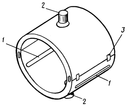
Fig. 1. A device for heating the shaft by a gas burner:
1 – slot; 2 – pocket; 3 – connecting strips
Induction heating of the conductor shaft is based on the appearance of eddy currents in it when it interacts with an inductor through which an alternating current flows, exciting an electromagnetic field. The energy of the magnetic field is converted into thermal energy [2].
Figure 2 shows the scheme of induction heating of the shaft section.
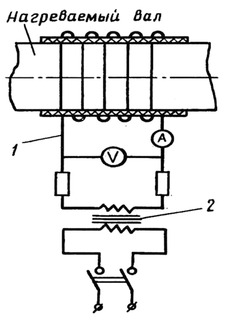
Fig. 2. Heating scheme of the shaft section:
1 – induction coil; 2 – transformer
The induction coil is powered by alternating current through a special transformer or from several welding transformers connected in parallel. The number of ampere turns of the coil is selected taking into account the diameter of the shaft in the heated place. The width of the coil depends on where it is installed, the cable cross-section should be no more than 200 mm2. To be able to control the speed and temperature of heating, the coil is wound in three or four sections, which can be switched on in any sequence.
Before installing the coil on the shaft, the latter must be insulated over the entire surface to be heated with an asbestos cord or an asbestos cloth 20 mm thick. The internal diameter of the inductor is determined by the diameter of the shaft, the thickness of the insulation and the clearance for free rotation of the shaft, equal to 10-12 mm per side.
Since the installation of the coil should not interfere with the rotation of the shaft when it is heated, the inductor is centered relative to the shaft and attached to the stand for straightening.
For regulation and maintain the temperature on a given level, the induction coil is connected to four welding transformers of the СТЭ-24У type connected in parallel. The circuit must include an ammeter and a voltmeter.
Rotation of the shaft is not necessary during induction heating.
For heating experimental samples of circular cross-section modeling shafts of various designs, in the research of straightening processes, tubular resistance furnaces with a heating element made of chromium-nickel alloy nichrome Х20Н80 are the most appropriate.
According to data [3], chromium-nickel heating elements using in resistance furnaces are designed for long-term use at heating temperatures up to 1000 °C. When operating the furnace, it is necessary to optimize the current value using an autotransformer. The optimal temperature is set changing the current value.
The heating element is the most important part in the resistance furnace. Working with heat it determines its operational capabilities. The following requirements are imposed on the material from which the heating element is made: heat resistance (scale resistance); thermal stability (with significant temperature changes, mechanical strength is maintained); high electrical resistivity, which ensures optimal length and cross-section of the heating element; low temperature coefficient of resistance; immutability of electrical properties (duration of operation does not change electrical resistance); plasticity.
Figure 3 shows the design of the resistance furnace for insulated windings.
The calculation of the resistance tube furnace for heating experimental samples is carried out in the following sequence. As a material for the heating element of the furnace, a wire made of chromium-nickel alloy nichrome X20H80 with a diameter of d = 0.8 mm with a specific electrical resistance of p = 1.1 Om·mm2/m and a cross-sectional area of 0.5 mm2 was selected.
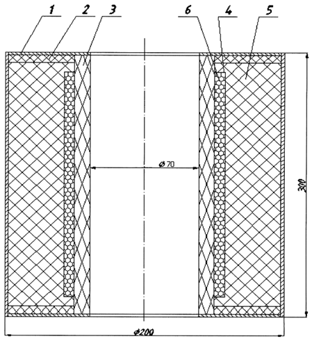
Fig. 3. Resistance heating furnace design:
1 – steel thermal cover; 2 – fire-resistant plate;
3 – ceramic pipe; 4 – spiral coating; 5 – thermal protection (mullite silica wool); 6 – chromium-nickel heating element
Initial data:
Device with power P = 1 500 W; voltage supplied to the device U = 220 V; heating temperature 650 °С.
Let's determine the current strength:
I = Р / U = 1 500 / 220 = 6.818 А.
Let's assume that the maximum current value is no more than 9A, let's calculate the active resistance:
R = U / I = 220 / 7 = 31.4 Om.
Let's determine the length of the chromium-nickel wire for the heating element:
l = R(s / ρ) = 31.4 · (0.5 / 1.1) = 14.27 m.
Let us determine the length of the heating element turn if the diameter of the ceramic pipe is 0.07 m:
C = πd = 3.14 · 0.07 = 0.22 m.
Let's determine the number of turns for a wire length of 13 m, leaving 1 m for connection to the power source:
n = 14.27 / 0.22 ≈ 59.
We will propose a design of two windings arranged in series, we will step back 20 mm from the fire-resistant plate for the installation of a heating element, the length of one section will be:
l1 = (300 – 2 · 20) / 2 = 130 mm.
Let's calculate the pitch of the heating coil:
l1 / n = 130 / 59 = 2.2 mm.
The inter-turn gap will be 1.4 mm. We accept the power of a tubular resistance furnace of no more than 1,5 kW, which according to data [3] is quite enough to warm up the sample for the entire cross-section.
With a gap of 1.4 mm between the coils, there is a danger of their contact during operation, which will lead to the burning out of the heating element and the interruption of the experiment. It is necessary to isolate the coils of the spiral from each other. It is proposed to isolate it with a heat-resistant composition consisting of betonite clay with chamotte crumbs (granules up to 2 mm). This composition does not react with scale at high temperatures, the spiral does not oxidize. Liquid glass can be used as a binding solution and prevent the destruction of the heat-resistant composition. Before assembling the resistance furnace, it is necessary to dry the coating from a heat-resistant composition well, which at a temperature of 20 °C will take up to a week and three hours when heated to 300 °C. It is recommended to carry out drying in natural conditions, this will prolong the service life of the resistance furnace. The heating element of the furnace will be connected to the power source in parallel. With a high current value, it is necessary to regulate it, which can be done by installing a rheostat in the electrical circuit. Figure 4 shows a possible connection diagram of a tubular resistance furnace [4].
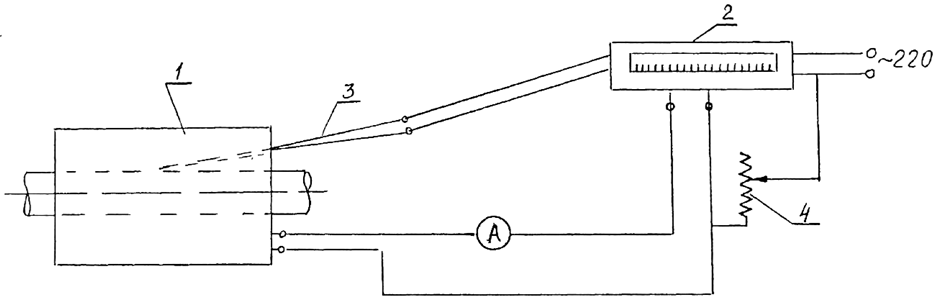
Fig. 4. Schematic diagram of the connection of a tubular resistance furnace: 1 – tubular resistance furnace;
2 – electronic potentiometer; 3 – thermocouple; 4 – rheostat
The designed furnace was manufactured and a trial local heating of the experimental sample was carried out. The heating time of the shaft to 650 °C was about three hours. A thermocouple was used to control the temperature. After the natural cooling of the experimental shaft, a control check for runout is performed.
Conclusion
Several methods of heating experimental shafts are considered. The heating of the shafts by a tubular resistance furnace is selected. The furnace is designed and manufactured for experiments. The uniformity of heating of the shaft for three hours to the required temperature of 650 °C, the availability of the materials used, their reliability in the experiment, confirmed the correctness of the choice of the heating method and the design of the furnace.
1. Viazankin V. V., Mamontov V. A. Vosstanovlenie deformirovannykh sudovykh valov pravkoi [Restoration of de-formed ship shafts by editing]. Vestnik Astrakhanskogo gosudarstvennogo tekhnicheskogo universiteta. Seriia: Morskaia tekhnika i tekhnologiia, 2023, no. 1, pp. 50-55.
2. Telegin A. S., Lebedev N. S. Konstruktsii i raschet nagrevatel'nykh ustroistv [Designs and calculation of heating de-vices]. Moscow, Mashinostroenie Publ., 1975. 280 p.
3. Ispytatel'naia tekhnika: spravochnik [Testing equipment: reference]. Pod redaktsiei V. V. Kliueva. Moscow, Mashi-nostroenie Publ., 1982. 528 p.
4. Kuznetsov M. I. Osnovy elektrotekhniki [Fundamentals of Electrical engineering]. Moscow, Vysshaia shkola Publ., 1964. 560 p.
