


Russian Federation
Astrakhan, Astrakhan, Russian Federation
The main material in the construction of hull structures of ships is shipbuilding steel. In shipbuilding and ship repair, welding plays a key role in forming the joints of steel structures. Every vessel in the Russian Federation is undergoing an inspection. During the inspection, the technical condition and compliance of the vessel with safety requirements are checked. During the inspection of body elements, especially welded joints, defects are often found, characterized by a violation of the continuity of the weld metal, while their parameters go beyond the limits established by regulatory documents. If the permissible standards are exceeded, the defects must be removed according to the factory's technology, and the welds must be repaired. Repair of defective areas leads to an increase in repair time, as well as an increase in the labor intensity and cost of repairing or building the ship's hull. The question becomes relevant: to eliminate the found defect or to allow the construction to be operated. The technology of manufacturing samples for conducting experimental research is considered. The choice of material, dimensions and shape for the manufacture of samples, as well as the technological parameters of the manufacturing process, are justified. The method of obtaining internal defects in a welded joint is described. According to the results of radiographic control, welded samples with an internal defect were identified, as well as control samples without defects. An experimental fatigue testing facility has been designed and constructed, which makes it possible to reproduce the necessary conditions. In addition to the installation, a computer program has been developed that allows you to count the number of cycles before the sample is destroyed, as well as read the corresponding deflection of the welded joints.
welding, welding defects, material fatigue, mechanical testing, shipbuilding steel
Introduction
The development of quality control methods for welded joints enables increasingly accurate determination of the location and configuration of defects. However, the difficulties associated with calculating stress concentration factors for various types of defects and assessing their impact on fracture initiation are so significant that there is little hope of overcoming them in the near future.
Fatigue assessment of welded joints is an important stage in designing and repairing welded hull structures. Fatigue testing of materials is conducted to determine specified mechanical characteristics using standard test methodologies [1]. Using these data, appropriate materials are selected for fabricating required components and structural elements, and strength calculations are performed [2]. Therefore, when considering the influence of defects in welded joints on the strength of hull structures, primary attention should be given to the methodology of experimental studies, selection of necessary materials, and processing of obtained results based on the principles of fracture mechanics.
The study [3] shows that fatigue ranks third among the causes of failure in steel welded structures subjected to fatigue. The methodology for testing full-scale samples may vary depending on the specifics of the object under investigation. There is a wide variety of cyclical material tests available [4–8]. When performing full-scale tests, existing testing machines, installations, and equipment of this type are typically bulky, expensive, and labor-intensive to operate, representing technically complex systems [9, 10].
Given the complexity of acquiring such installations and the specificity of tasks being addressed, it becomes relevant to develop a kinematic scheme and manufacture an experimental setup independently. The installation makes it possible to reproduce the necessary test conditions for the studied experimental samples and does not require costly maintenance.
Fatigue tests are one of the main directions in analyzing operational safety, strength, reliability, and durability of such parts.
Research methods and materials
Any experiment should be organized in such a way that the technology for manufacturing experimental samples and their testing ensures maximum approximation to real conditions. Rules of the FAI “Russian Maritime Register of Shipping” and other classification societies provide for the use of shipbuilding steel grades PCA, PCB, PCD, etc., for the manufacture of marine vessel hull structures.
For conducting fatigue tests, particularly bending-torsion tests, the size and shape of the test specimens are determined in accordance with ISS 25.502-79 [11]. In order to manufacture the specimens, initially twelve identical rectangular plates measuring 175×125×20 mm were cut from sheet stock of PSD40 grade steel using guillotine shears. These plates were then welded together, resulting in six welded plates with defects.
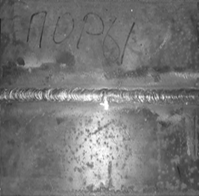
Welding of the plates was carried out using manual arc welding with a consumable electrode, performed in the flat position with X-shaped edge preparation. Edge preparation was done according to connection type C25 in accordance with ISS 5264-80 [12]. Welding was carried out using electrodes of category 3Y40NNN following optimal modes for this type of connection (Fig. 1).
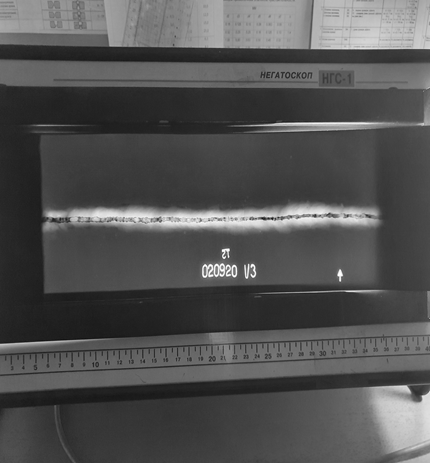
Defect formation was simulated by using un-dried electrodes, poor cleaning before welding, introducing slag and oil into the weld pool. Prior to turning and milling operations, the welded plates underwent radiographic examination followed by decoding of the images (Fig. 2). In order to ensure that the test specimen contained precise defects, marking was made using a template (Fig. 3) on the plates with defects.
After marking, rectangular specimens measuring 350×20×20 mm were cut out on a milling machine, taking measures to avoid surface hardening and metal overheating. Subsequently, the rectangular specimens were subjected to lathe machining.
 |
Test piece R1; test length L ≥ 350 mm; width B of the test piece ≥ 250 mm
|
|
a |
b |
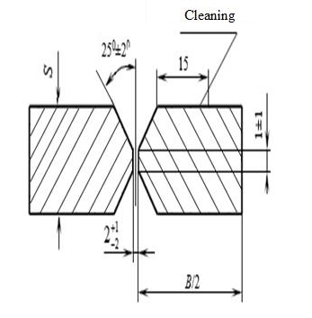
Fig. 1. Welded plates with defects: a – photo welded wear plate; b – pattern of gouging edges for welding
|
Fig. 2. Decoding of images on NGS-1 apparatus |
Fig. 3. Marking of plates |

Turning of grooves in the specimens was carried out on a 16K20F3S32 model lathe. As a cutting tool, a threaded cutter with an angle at the vertex of 45° and a radius at the vertex of the cutter of 0.1 mm was chosen. The material of the cutter blade was titanium-cobalt alloy TK5K10. During turning, the workpiece and the cutter were abundantly cooled with emulsion. As a result of turning operations, final specimens (Fig. 4) with predetermined characteristics suitable for fatigue testing were obtained.
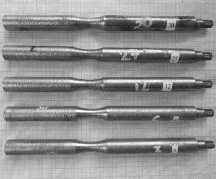
Fig. 4. Specimens for fatigue testing
To investigate the effect of defects in the weld joint of the resulting specimens, a device for testing specimens for fatigue was developed [13]. Figure 5 presents the schematic diagram of the installation. The installation consists of a base 1, on which a drive unit 2 is mounted, with a rigidly fixed grip 3 attached to it for cantilever mounting of the specimen 4. At the free end of the specimen 4, a cage 5 with radial bearings is installed, secured with metallic fasteners 6. Perpendicular to the axis of the grip, there is an additional calibrated spring 7, one end of which is connected to the fastener 6, while the other end supports a load 8. On the calibrated spring, a cargo position sensor 9 is rigidly mounted, and on the grip, a rotation counter 10 is installed and securely fixed.
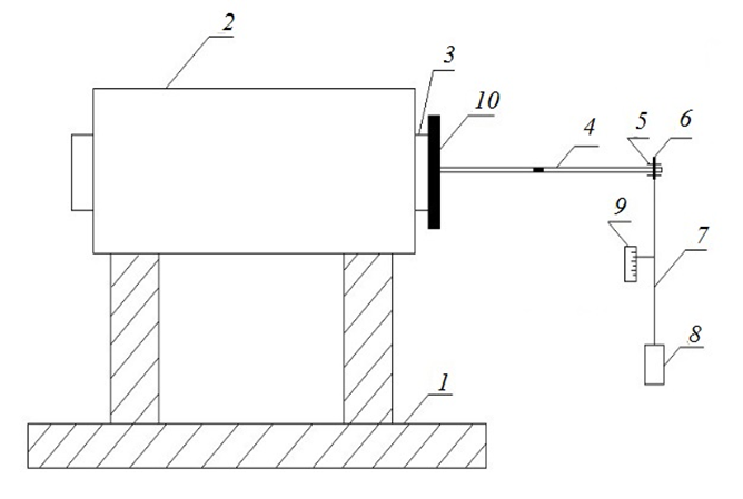
Fig. 5. Installation for fatigue testing of specimens
During operation of the installation, a pulsating load is applied to the specimen, causing bending stresses. Upon reaching critical loads, the specimen begins to deform. There is a sharp displacement of the load by a large magnitude of free oscillations. The recording device, located separately from the main device, records the position of the load and the rotation counter, transmitting readings to a computer. The collected data provides insight into the state of the specimen under cyclic loading.
Load variation is achieved by using interchangeable weights of different masses. Samples with artificial cracks or welds undergo fatigue testing until complete destruction of the sample or weld occurs. During this time, both the duration of the tests and the number of cycles during experiments are recorded.
A specialized software program was developed for the operation of the installation, for which a certificate of state registration was obtained [14].
Figure 6 shows a graph of sample deformation versus cycle count.

Fig. 6. Sample deformation graph
The program is used to calculate the number of oscillations and measure the corresponding deflection of welded joints by counting pulses from the sensor and receiving values from the analog-to-digital converter integrated into the controller, to which a resistive position sensor is connected. Additionally, the program constructs a graph on the computer showing the dependence of sample deformation on the number of cycles based on the received data from the controller. Together, the fatigue testing installation and the computer program will enable determining the endurance characteristics of the samples.
Conclusion
1. The technology for manufacturing specimens for fatigue testing of welded joints in laboratory conditions has been detailed.
2. A laboratory installation for conducting fatigue tests has been developed, constructed, and its operation thoroughly described. The installation expands the functional capabilities of testing equipment, enabling testing of specimens under cyclic bending with torsion under symmetric stress cycle changes.
3. A computer program has been developed that allows determining the deflection of welded joints up to their complete failure.
4. The test results will be utilized to address issues related to the operability of welded joints containing internal defects.
1. Shkol'nik L. M. Metodika ustalostnykh ispytanii: spravochnik [Fatigue testing methodology: a reference book]. Moscow, Metallurgiia Publ., 1978. 304 p.
2. Gadolina I. V., Makhutov N. A., Erpalov A. V. Varied approaches to loading assessment in fatigue studies. Interna-tional Journal of Fatigue, 2021, vol. 144, p. 106035.
3. Beliaev B. F. Prochnost' svarnykh soedinenii s defektami pri nizkikh temperaturakh [Strength of defective welded joints at low temperatures]. Vybor i obosnovanie metodov i norm kontrolia kachestva svarnykh soedinenii: sbornik nauchnykh trudov. Leningrad, Izd-vo Leningradskogo doma nauchno-tekhnicheskoi propagandy, 1976. Pp. 45-52.
4. Gromov V. E., Ivanov Yu. F., Vorobiev S. V., Konovalov S. V. Fatigue of Steels Modified by High Intensity Electron Beams. Cambridge, Cambridge International Science Publishing Ltd., 2015. 272 p.
5. Mughrabi H., Christ H.-J. Cyclic deformation and fatigue of selected ferritic and austenitic steels: specific aspects. ISIJ International, 1997, vol. 37, iss. 12, pp. 1154-1169.
6. Suresh S. Fatigue of Materials. Cambridge, Cambridge University Press, 1998. 679 p.
7. Anosov A. P. Otsenka resursa sudovykh konstruktsii v usloviiakh tsiklicheskogo nagruzheniia: dis. … d-ra tekhn. nauk [Assessment of the resource of ship structures under cyclic loading conditions: dis. … Doctor of Technical Sci-ences]. Vladivostok, 2001. 371 p.
8. Terent'ev V. F., Korableva S. A. Ustalost' metallov [Metal fatigue]. Moscow, Nauka Publ., 2015. 484 p.
9. Ruban R. A., N'ian N., Chanchikov V. A., Nikul'shin A. V. Ustanovka dlia ispytanii obraztsov na ustalost' [Fatigue testing facility for samples]. Patent RF, no. 2014130275/28, 27.11.2014.
10. Kolotnikov M. E., Soliannikov V. A. Ustanovka dlia ispytaniia obraztsov pri dvukhchastotnom nagruzhenii [In-stallation for testing samples under two-frequency loading]. Patent RF, no. 93005689/28, 20.07.1998.
11. GOST 25.502-79. Raschety i ispytaniia na prochnost' v mashinostroenii. Metody mekhanicheskikh ispytanii me-tallov. Metody ispytanii na ustalost' [ISS 25.502-79. Calcula-tions and strength tests in mechanical engineering. Methods of mechanical testing of metals. Fatigue testing methods]. Available at: https://www.testprom.ru/img_user/gosts/77/040/gost_25.502-79.pdf (accessed: 08.08.2025).
12. GOST 5264-80. Ruchnaia dugovaia svarka. Soedi-neniia svarnye. Osnovnye tipy, konstruktivnye elementy i razmery [ISS 5264-80. Manual arc welding. The joints are welded. Main types, structural elements and dimensions]. Moscow, Standartinform Publ., 2010. 35 p.
13. Kozhukhar' E. D., Ruban A. R., Shakhov V. V. Ustanovka dlia ispytanii obraztsov na ustalost' [Fatigue testing facility for samples]. Patent RF, no. 2022108243, 21.12.2022.
14. Shakhov V. V., Kozhukhar' E. D., Ruban A. R. Predel ustalosti [Fatigue limit]. Svidetel'stvo o gosudarstvennoi registratsii programmy dlia EVM 2022680827 Rossiiskaia Federatsiia, no. 2022680057, 07.11.2022.
