Россия
Одной из тенденций развития морской техники является постоянное увеличение степени электрификации судов. Этот процесс сопровождается и повышением опасности судовых электросетей, определяемой в первую очередь работой электроустановок с однофазным повреждением изоляции. Последствия такого режима во многом зависят от фазной емкости электросети, при этом влияние фазной емкости на опасность однофазных замыканий обусловлена не только ее величиной, но и степенью несимметрии. Доказывается, что именно несимметрией фазных емкостей вызвано формирование в судовых электрических сетях напряжения нулевой последовательности. Выполнен анализ показателей основных опасностей электрической сети с учетом влияния на них напряжения нулевой последовательности. Подтверждено, что в электросетях с изолированной нейтралью время срабатывания защиты на отключение токов однофазных прикосновений необходимо выбирать с учетом того, что бортовые сети могут обладать несимметричными фазными емкостями. Проведен комплекс теоретических и экспериментальных исследований оценки влияния напряжения нулевой последовательности на количественные показатели опасности судовой электросети. Выполнена экспериментальная оценка влияния несимметрии фазных емкостей на устойчивость электрических разрядов при однофазных замыканиях в электросетях с изолированной нейтралью. Продемонстрировано, что при замыканиях через неустойчивый электрический разряд наличие напряжения нулевой последовательности приводит к значительному повышению таких показателей взрыво- и пожароопасности электросети, как мощность и энергия, выделяющиеся в месте повреждения изоляции. Выявлено, что повышение безопасности может быть достигнуто за счет воздействия на величину напряжения на нейтрали.
однофазные замыкания, несимметрия, напряжение нулевой последовательности, изолированная нейтраль, электроопасность, пожаро- и взрывоопасность
Introduction
The safety of electric networks in marine equipment is mainly determined by the single-phase fault mode. This type of fault generally occurs in ship power networks and can cause major accidents [1]. Since power networks of ships operate with an insulated neutral, such faults are characterized by a relatively low current at the insulation break location that does not result in the disconnection of the damaged network section. Thus, single-phase faults may exist for quite a long time in the existing ship power systems before the crew localizes them [2]. As a rule, phase capacity, a value that determines the current values of single-phase faults in low-voltage ship power networks, is not controlled. Additionally, there are pieces of marine equipment that feature cable lines longer than a thousand kilometers and a specific phase capacity of 200 nF/km [3]. Fault currents generated in such power networks become comparable to load currents.
Besides, ungrounded-neutral power networks typically feature neutral displacement along the alternating potential. This increases the risks associated with single-phase faults like electric shock [4], combustion, and explosion. This is why it is important to assess the respective safety criteria. While the impact of the network phase capacity on the consequences of single-phase faults has been studied in detail, the assessment of the effects of neutral displacement on the safety of low-voltage ship power networks has not been performed. The purpose of this article is to study the impact of the zero-sequence voltage on the key threat parameters of ship power networks during single-phase faults.
The analysis of the causes of zero-sequence voltage in an insulated-neutral power network
Ship power networks with an ungrounded neutral typically generate zero-sequence voltage [5]. This voltage primarily occurs due to the asymmetry of the ship’s power system [6]. The ship’s power source and consumer voltages, as well as phase voltages against the hull, can be asymmetrical in the general case [7]. If the said phase voltages are different, zero-sequence voltage occurs.
The asymmetry of ship power sources is virtually impossible. However, there can be voltage asymmetry in consumers and against the hull. The asymmetry of phase voltages in consumers and the associated neutral displacement may occur due to the uneven distribution of single-phase loads across the phases of the power system connected to line voltage on board the ship. However, the asymmetry of consumers does not result in the formation of zero-sequence voltage. It emerges due to the asymmetrical lateral parameters of cable lines that power single-phase consumers [8].
Zero-sequence voltage in an insulated neutral power network is the neutral displacement of the source U0 against the hull. It can be calculated using this formula:

where Up is the phase voltage of the source; YA, YB, YC are complex phase conductivities of a three-phase power network.
When the supply voltages of the source are symmetrical, zero-sequence voltage U0 can only occur in a power system due to two reasons:
- the asymmetry of the active conductivity of phase insulation to the hull;
- the asymmetry of phase capacities against the hull.
When there is an asymmetry in the active component of phase insulation conductivity to the hull, voltage U0 (ceteris paribus) will increase in inverse proportionality with the shunting capacity of the conductors.
The active insulation resistance on board ships can be tested using a continuous control device and it usually amounts to single- or double-digit figures in megaohms. Phase capacity values are within the range of 0.5-20 uF per phase [9]. This corresponds to a capacitive reactance of about 150-6 500 Ω. Zero-sequence voltage in ship power systems is primarily associated with the asymmetry of phase capacities which is not normally controlled by any instruments during operation and can cause asymmetry at any conductivity values.
The experience of operating medium-voltage power networks that have a regulated asymmetry restriction [10] shows that preventing neutral displacement is not always possible in practice [11].
Safety parameters during single-phase faults
Single-phase faults are considered dangerous as they can cause electrocution (electric shock hazard), combustion at the insulation damage location (fire safety), and explosion when they occur in an explosive environment.
Following USS 12.1.038-82, electrical safety criteria may include the current passing through the human body when it touches the power system. Safe values for this current depend on the exposure time and other factors [12]. The electrical safety assessment for the power system is performed by measuring the current through a resistor with resistances ranging from 0.85 to 6.7 kΩ connected between the power system phases and the ground.
Additionally, some authors introduce a single-parameter safety assessment criterion that establishes a correlation between the maximum current value that is safe for a human and its duration, e.g. the following formula [13]:
![]() (1)
(1)
where Ik is the current passing through the human body; t is the duration of current passage through the human body; k is the factor depending on the human body weight.
The fire and explosion safety criteria for the ship power network include a high probability of the ship's condition that prevents fire outbreaks and exposure of the crew to the respective dangerous effects. These can be caused by the thermal energy produced at the electrical fault location. Quantitatively, it can be assessed using the following criteria:
1. Maximum current passing through the damaged spot imax [14].
2. Maximum power generated [15] at the damaged spot, which can generally be represented as
pmax = max(u(t)i(t)), (2)
where u(t) is the voltage at the fault location; i(t) is the fault current.
The authors of [16] demonstrated that the following expression can be used to assess the maximum heat release rates during a sustained single-phase fault:
pmax = 1.5Up2ωC, (3)
where Up is the phase voltage of the power network; ω is the angular power network frequency; C is the phase capacity of the power network.
3. The energy released at the damaged spot [17]:
 (4)
(4)
where t1, t2 are the start and end moments of the phase to hull fault.
For steady processes, the energy can be evaluated as follows:
W = 3CUp2. (5)
These criteria can be used to assess the possibility of electric shocks while working with the electrical equipment, as well as the possibility of its insulation or flammable materials near the damage point catching fire.
Results of the experimental assessment of zero-sequence voltage effects on safety
Experimental research into the effects of zero-sequence voltage generated by the asymmetry of phase capacities on the safety parameters listed above was conducted using a physical power network model whose layout is shown in Fig. 1.
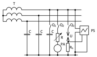
Fig. 1. Experimental setup layout:
Т are power source windings; С is the phase capacity of the power network; Q1, Q2, Q3 are switches; R is resistance;
PA is the amperemeter; U is the spark gap;
Rb is the instrument shunt; PS is the oscillography
The model included a triple-phase 380 V voltage source represented by transformer Т and a power network set with concentrated capacities С. To create asymmetry, one of the power network phases was disconnected with the Q1 switch. During the experiments, we registered single-phase touch currents pierced through resistance R whose value was selected following USS 12.1.038-82, as well as voltages and resistances of sparking processes that occurred while imitating insulation damage in the cable network. To create a damaged insulation model, we used a KNR-type cable as the spark gap U.
According to the USS, the electrical hazards rating of the network during normal operation can be assessed by measuring the current of a single-phase fault through a 6.7 kΩ resistance. To assess the safety of the power system in emergency mode, we can use the fault current passing through a resistance of 0.85-1 kΩ for industrial settings and 1-6 kΩ for household settings. The results of single-phase touch current registration are shown in the Table.
Touch current measurement results
|
Resistance R, kΩ |
Single-phase touch currents, A |
|
|
Symmetrical |
Asymmetrical |
|
|
0.85 |
0.25 |
0.37 |
|
6 |
0.037 |
0.055 |
|
6.7 |
0.033 |
0.049 |
The Table shows that the current exceeds the safe value of 0.3 mA during contact with the conductive parts of the power system operating in the normal mode. In the emergency mode, the touch currents of industrial power systems must be disconnected within 0.1 s, and in household systems within 0.6 s when the phase capacities are symmetrical or 0.4 s when those are asymmetrical. The comparison of the two modes using expression (1) showed that the permitted current duration during asymmetry shall be reduced by more than twice.
The mode comparison based on the maximum current through the damaged spot showed that the presence of phase capacity asymmetry increases the fire hazard by almost 1.5 times. The same proportion was obtained for the maximum heat release ratings calculated following (3) for various ship power network modes. According to (5), the amount of energy released during single-phase insulation damage in a network with asymmetrical capacities is over 2 times higher than that of a symmetrical capacity network.
Additionally, the asymmetrical power networks are more dangerous because of the free current components that occur as a result of the transient process during single-phase faults. These can be caused by the changing of the charge in the undamaged phase capacitances, damaged phase capacitance discharge, and charge exchange between interphase and phase capacitances while equalizing their voltages. The last two components attenuate quickly enough and do not have any significant impact on the hazard criteria reviewed above. Thus, the full fault location current, e.g. when phase A insulation is damaged, can be calculated as follows:

where CB, CC are the capacities of the undamaged phases; uB, uC are the voltages of the undamaged phases.
The voltages on the insulation of undamaged phases uB and uC after the fault include the forced and free components determined by the voltage in the damaged phase the moment before switching. The free components of these voltages help generate the free components of the single-phase fault current if(t) that can be described as follows:
if(t) = (CB + CC)uA(t1)exp(–δt)(δcosω0t + ω0sinω0t),
where uA(t1) is the damaged phase voltage at the moment of fault; δ is the attenuation factor of the transient process; ω0 is the frequency of the free component.
The voltage uA(t1) is mainly determined by the voltage of the neutral displacement along the constant potential and the zero-sequence voltage. Thus, one should expect an increase in the risks associated with the free components of the fault current when the network becomes asymmetrical.
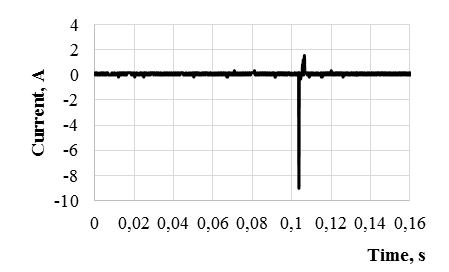
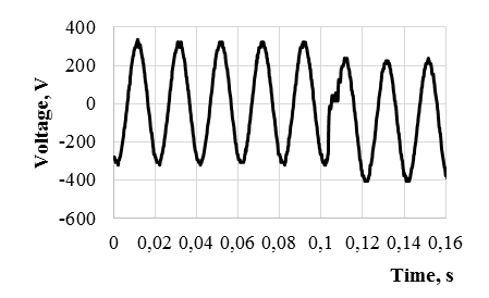
Fig. 2 below shows the examples of current and voltage oscillograms of the damaged phase in a symmetrical power network when there is arcing in the damaged insulation section.
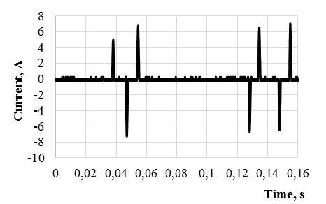
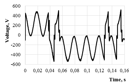
As we can see from Fig. 2, the arcs proved unstable, and the duration of each of them did not exceed half a period of the free oscillation frequency. Longer electric arcs occurred when phase capacities were asymmetrical (Q1 in Fig. 1 is off). Fig. 3 provides the examples of registered current and voltage oscillograms during single-phase insulation damage in a network with asymmetrical phase capacities.
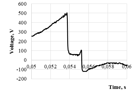
As we can see from Fig. 3, the fault passes through an unstable arc that goes out as soon as its current transgresses the zero value. The oscillograms provided here show seven faults in total. The voltage oscillogram shows that faults are accompanied by arcs with relatively high resistance.
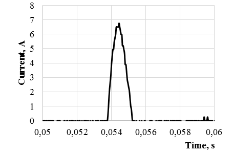
To assess the quantitative hazard criteria, we selected a section of the oscillogram between 0.05 and 0.06 s. Changes in current and voltage over this period are shown in Fig. 4.
a b
Fig. 2. The fault current (a) and damaged phase voltage (b) oscillograms in a symmetrical power network
a b
Fig. 3. The fault current (a) and damaged phase voltage (b) oscillograms in a network
with asymmetrical phase capacities
a b
Fig. 4. Current (a) and voltage (b) oscillogram sections in the single-phase fault location
The highest instant fault current value in the oscillogram section in question is 6.24 A, which is several times higher than the maximum value of the normally registered steady solid fault current, which is 1.24 A in this power system.
Changes in the heat release rate that occur when there is arcing in the period in question are shown in Fig. 5.
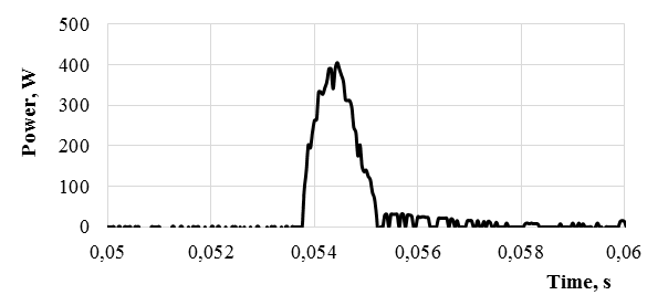
Fig. 5. Power changes at the single-phase fault location
The maximum power value calculated using the oscillogram and following (2) made 405.8 W. If we consider only the steady processes under expression (3), its value shall make 114.4 W, which is several times lower than the unstable arcing fault mode. Similar results were obtained for the energy produced during the arcing. Following (4) and the registered oscillograms, it reached 5.99 J, which is by an order of magnitude more than the steady fault value calculated with (5).
Conclusion
Based on the conducted theoretical and experimental research, we established the following:
- The asymmetry of phase capacities in ship power systems with an insulated neutral can affect their electrical safety. When assessing the permitted protection system tripping time, it is necessary to consider the most adverse phase capacity asymmetry mode.
- The experiments showed that phase capacity asymmetry can facilitate the formation of stable electric arcs during single-phase insulation damage.
- Single-phase faults through an electric arc or a spark are the most dangerous ones. Even if they exist for a short time, the associated fire and explosion safety parameters like the maximum damaged spot current, power, and heat release energy exceed the same values for stable faults through transient resistances.
- The theory and experimentation show that the presence of zero-sequence voltage helps increase the free component of single-phase fault currents. During arcing faults, this causes in a significant reduction of the network's fire and explosion safety. Thus, controlling the voltage in the neutral can be an effective method of improving the safety of ship power networks.
1. Prousalidis J. On improving the earthing quality in ship electric energy systems // Journal of Marine Engineering and Technology. 2019. V. 18. N. 1. P. 46–55.
2. Кажекин И. Е., Харитонов М. С. Результаты статистического исследования видов однофазных замыканий в низковольтных судовых электросетях // Вестн. Мурман. гос. техн. ун-та. 2023. Т. 26. № 4. С. 431–440.
3. Meijer C., van der Ven J. K., Ross R. EMC and electrical safety on board ships how EMI filters undermine the protection against electric shock // 2013 International Symposium on Electromagnetic Compatibility. IEEE, 2013. P. 1034–1038.
4. Utegulov B. Special issues of ensuring electrical safety in networks with isolated neutral voltage up to 1000 V at mining enterprises // Industrial Engineering. 2018. P. 1–29.
5. Fulczyk M. Zero-sequence components in unit-connected generator with ungrounded neutral during ground-faults // PowerCon 2000. 2000 International Conference on Power System Technology. Proceedings (Cat. No. 00EX409). IEEE, 2000. V. 2. P. 831–836.
6. Xu X., He M., Zheng H. Study of electric power quality improvement in ship networks // 2006 1ST IEEE Conference on Industrial Electronics and Applications. IEEE, 2006. P. 1–6.
7. Губанов Ю. А. Воспроизведение отклонений параметров качества корабельной сети в условиях испытательного стенда // Электропитание. 2009. № 4. С. 37–44.
8. Barros J., Diego R. I. A review of measurement and analysis of electric power quality on shipboard power system networks // Renewable and Sustainable Energy Reviews. 2016. V. 62. P. 665–672.
9. Tarnapowicz D. Reduction of the fire risk in the aspect of ground currents in ship electrical grid LV type IT // 2016 International Conference on Information and Digital Technologies (IDT). IEEE, 2016. P. 280–287.
10. Правила технической эксплуатации электрических станций и сетей Российской Федерации (ПТЭЭСС). М.: Мини Тайп, 2023. 300 с.
11. Барсков В. В., Кириченко А. Н., Щекочихин А. В. Напряжения несимметрии в кабельных сетях 6кВ // Динамика систем, механизмов и машин. 2014. № 1. С. 181–184.
12. ГОСТ 12.1.038-82. Система стандартов безопасности труда. Электробезопасность. Общие требования и номенклатура видов защиты. М.: Госстандарт России, 1985. URL: https://www.ruscable.ru/doc/docgost/files/88320836122.pdf (дата обращения: 21.05.2024).
13. Никольский О. К., Халина Т. М., Куликова Л. В. Системы техногенной безопасности электроустановок до 1000 В. М.: Директ Медиа, 2023. 324 с.
14. Буре И. Г., Хевсуриани И. М. Особенности построения защиты от токов однофазного короткого замыкания в распределительных сетях до 1 кВ // Вестн. Моск. энергет. ин-та. 2010. № 5. С. 48–53.
15. Зыков В. И., Малашенков Г. Н. Моделирование пожарной опасности проводов и кабелей электрических сетей // Пожары и чрезвычайные ситуации: предотвращение, ликвидация. 2009. № 3. С. 45–52.
16. Жилин О. И. Пожарная безопасность электроустановок // Энергобезопасность и энергосбережение. 2007. № 4. С. 19–31.
17. Никифоровский Н. Н., Брунав Я. П., Татьянчен-ко Ю. Г. Электропожаробезопасность судовых электрических систем. Л.: Судостроение, 1978. 120 с.

