Россия
Россия
Россия
Россия
Россия
Рассмотрены условия трения и смазывания подшипников скольжения в судовом дизеле. В условиях переходных режимов, больших нагрузок или загрязнения смазочного материала, используемого в подшипниках скольжения судовых дизелей, смазочная пленка становится достаточно тонкой с толщиной в диапазоне 0,25–2,5 мкм, а местное давление достаточно большим – порядка 15–20 МПа. При этом для работы подшипников скольжения в гидродинамическом режиме минимальным является давление в смазочной системе Р = 0,05 МПа, иначе вместо гидродинамического клина между шейкой коленчатого вала и вкладышем образуется зона граничного трения. Предложен способ повышения триботехнических свойств смазочных материалов в парах трения скольжения путем применения запатентованной противоизносной присадки на основе диселенида молибдена MoSe2 и жирных кислот. Проведена оценка триботехнических характеристик модифицированных смазочных материалов с использованием противоизносной присадки «Нанотекс-12» в условиях, моделирующих работу реального подшипника скольжения коленчатого вала судового дизеля 6ЧНСП 18/22 на машине трения 2070 СМТ-1. Переменными условиями изнашивания деталей моделируемого подшипника скольжения являлись давление на контакте трущихся поверхностей и концентрация противоизносной присадки (по объему) в смазочном масле М-16Г2ЦС. В результате проведения расчетных и экспериментальных исследований получены графические зависимости износа, интенсивности изнашивания и износостойкости моделируемого узла трения от величины объемной концентрации Сi противоизносной присадки в смазочном масле и контактного давления Рi. Подтверждено, что применение присадки в смазочном масле М-16Г2ЦС значительно улучшает его триботехнические характеристики, поскольку износ пары трения снижается на 5–15 %, интенсивность изнашивания снижается на 7–17 %, а износостойкость повышается на 6–18 % в зависимости от концентрации присадки в смазочном материале. Снижение износа вкладыша подшипника скольжения в случае применения противоизносной присадки (по сравнению с бесприсадочным смазочным маслом) создает основания к ее успешному применению в судовых маслах, но повышение концентрации присадки в масле свыше 2,0 % по объему является нецелесообразным ввиду ухудшения триботехнических характеристик и снижения экономической эффективности таких смазочных композиций.
смазочное масло, судовой дизель, подшипник скольжения, коленчатый вал, вкладыш, противоизносная присадка, жирные кислоты, диселенид молибдена
Introduction
The most important and heavily loaded moving units of a marine diesel engine are the cylinder-piston group and the crank mechanism due to significant operating temperatures (up to 100-110 °C) and contact pressures in tribocouplings (up to 20 MPa) [1]. At the same time, the crank mechanism has specific features of friction and wear, as well as technical maintenance and repair during the operation of marine equipment, which is carried out as part of major engine repairs, when the crankshaft is re-laid in new bearings. While repair of cylinder-piston group parts is carried out during routine and medium repairs of the diesel engine. It should be noted that failure of frame and connecting rod bearings of a diesel engine due to extreme wear of friction pairs, as well as the crankshaft, requires the ship owner to stop operating the vessel and put it in for repairs, which results in significant costs in the range from 150 000 rubles to several million, as well as long downtime of ships [2]. In this regard, the task of increasing the wear resistance and service life of sliding bearing pairs of the crank mechanism of marine diesel engines seems relevant, which can be solved by implementing various design and technological proposals [3]. From the point of view of technical and economic justification and tribotechnical efficiency, one of the optimal solutions is the development and use of anti-wear additives to motor lubricating oils. For this purpose, the additive Nanoteks-12 was developed and patented, which contains a layered modifier – molybdenum diselenide, as well as a number of fatty unsaturated acids, which are surface-active substances [4].
The purpose of the lubricant is to separate one friction surface from another with a thin boundary layer, while the rubbing surfaces should not experience damage. It is necessary that the layer of lubricant between the friction surfaces has a sufficient thickness, ensuring the absence of contact of the working surfaces with a certain roughness, which helps to reduce wear of parts [5].
The type of lubricant and the dimensions of the surfaces of the plain bearings are selected in such a way as to ensure the conditions of liquid friction of metal surfaces. This type of lubrication in marine diesel engines is called liquid or hydrodynamic lubrication, usually represented by mineral or synthetic oils [6]. In this case, for the operation of plain bearings in the hydrodynamic mode, the minimum pressure in the lubrication system is P = 0.05 MPa, otherwise, instead of a hydrodynamic wedge, a boundary friction zone is formed between the crankshaft journal and the liner [7, 8]. Bearings operating under boundary friction conditions are calculated using a conventional method. First, the average pressure pa between the shaft and the liner is limited, which ensures wear limitation and non-squeezing of lubricant between the working surfaces of the bearing liner and the shaft. Second, according to the product pav (v is the peripheral speed of rotation of the shaft), the “shaft – liner” pair is calculated for heating in order to ensure normal thermal operation of the bearing. The product pav characterizes the specific friction power, therefore, when the permissible value [pav] is exceeded, the temperature locally increases so much that a rupture of the oil layer occurs, and, as a result, the seizure of the surfaces of the shaft and liner.
Conditions for normal operation of plain bearings under boundary friction conditions [9]:
pa ≤ [pa];
pav ≤ [pav],
where pa – the actual average pressure between the journal and the liner, MPa; v – the peripheral speed of the shaft, m/s; [pa] – the permissible pressure, MPa; [pav] – the permissible value of the criterion, which for the bearings of the crank mechanism of a marine diesel engine is 12-18 (MPa·m)/s at an allowable pressure in the range of [p] = 15-20 MPa.
Under transient conditions associated with engine starts and stops, when the crankshaft rotation speed is up to 0.3 m/s, high loads or contamination of the lubricant used in the plain bearings of marine diesel engines, the lubricating film becomes thin enough with a thickness in the range of 0.25-2.5 μm, and the local pressure is quite high – about 15-20 MPa [7]. With a decrease in the sliding speed or an increase in the load, the lubricant layer can become so thin that there is a possibility of rupture of the lubricating film and the associated phenomenon of direct contact of the rubbing surfaces. In this case, the load is borne by the molecular layer, usually consisting of long chain molecules of fatty acids adsorbed by metal surfaces. One of the ways to create a shear-resistant lubricating layer is to add active compounds to the lubricating oil – sulfides, chlorides, succinamides, dichalcogenides, which can be contained in various additives, additives and modifiers for lubricants [10, 11]. These compounds are either adsorbed independently or contribute to the creation of a stable cladding layer with improved tribotechnical characteristics on the friction surfaces. In the absence of such a chemically stable protective layer, welding of friction surfaces under pressure, rupture of joints and destruction of these surfaces may occur, which ultimately leads to their mutual seizure and failure of friction pairs in plain bearings of marine diesel engines. On the other hand, if we consider the mechanism of lubrication with a small film thickness in the friction zone, then as the thickness of the lubricating layer decreases, most of the load is transferred to the roughness projections of the rubbing surfaces, and provided that a molecular layer with the required tribotechnical characteristics exists, the probability of welding in the friction pair is significantly reduced. With the standardized ranges of load values and sliding speeds in the friction unit, the cladding molecular layer is firmly held on the rubbing surfaces due to molecular adsorption. The active molecules that form the protective layer are mainly long chain molecules of fatty acids. When combined with the material of the crankshaft of a marine diesel engine, these molecular chains form iron soaps based on various acids formed by oxidation of the lubricants used. To form iron soap, a fairly weak concentration of acids in the oil is required – about 0.1%. This lubrication system is called boundary lubrication, and the main phenomenon detected during operation of the friction unit under such lubrication conditions is the value of the friction coefficient f = 0.1 and lower. The value of f under such conditions does not depend on the magnitude of the load and sliding speed [12].
When there is no lubricant in the friction zone or the fatty acid chains are broken, the friction coefficient f is close to 0.1. Therefore, such a layer, provided under conditions of adding additives to lubricants, must be stable, that is, the concentration of additives must satisfy the conditions of adsorption of fatty acid chains on the friction surfaces [13].
Based on the above, the main factors that have a significant impact on the wear resistance of plain bearings of marine diesel engines should be considered the pressure in the friction zone of the bearing parts, the mechanical and tribological characteristics of the materials from which they are made, as well as the concentration of additives in lubricants, on which the strength of the oil film and the durability of the required lubricating properties of oils depend.
The conducting of a tribological research
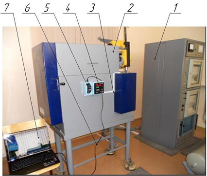
The main objective of the research is studying the tribological characteristics of modified lubricants using the anti-wear additive Nanoteks-12 under conditions simulating the operation of a real plain bearing of the crankshaft of a 6ChNSP 18/22 marine diesel engine using a 2070 SMT-1 friction machine (Fig. 1) [14]. The 6ChSPN 18/22 diesel engines are four-stroke, trunk-type, with vertical cylinders, non-reversible, with gas turbine supercharging and intermediate air cooling, right and left models, right and left rotation of the crankshaft [1]. The variable wear conditions of the simulated plain bearing parts were the contact pressure of the rubbing surfaces and the concentration of the additive (by volume) in the M-16G2CS lubricating oil [15]. In the work, the wear conditions of the friction pair “shaft journal – bearing shell” were varied for three variants of pressure Pi and volume concentration of additive Ci in the lubricant. The composition Nanoteks-12 was selected as an anti-wear additive, containing 10% by weight of molybdenum diselenide and 90% of fatty acids, which are a mixture of oleic and stearic acids. The patent formula of this additive is given in [4]. The range of values of the volume concentration of the additive in the lubricant was C = 0-2.0% with a step of Ci = 1.0% (Fig. 2), the range of values of the contact pressure was P = 0.1-0.7 MPa with a step of Pi = 0.3 MPa.
a b
Fig. 1. The friction machine 2070 SMT-1: a – the general view: 1 – a friction machine control unit;
2 – a friction machine; 3 – the switching wires connecting the temperature sensor with the recorder; 4 – a recording device;
5 – a converter; 6 – the switching wires; 7 – a personal computer;
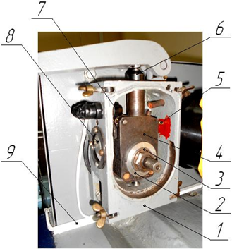
b – the test chamber: 1 – a housing; 2 – a fixed sample; 3 – a movable sample; 4 – a sample holder;
5 – a temperature sensor; 6 – a loading unit; 7 – the lighting lamps; 8 – a window; 9 – the switching wires
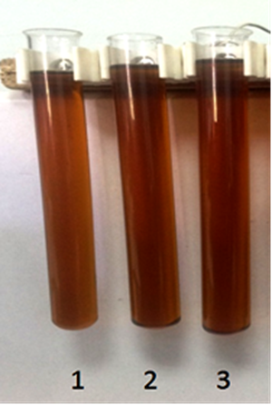
Fig. 2. The samples of the lubricants for tribological testing: 1 – an oil M-16G2СS; 2 – a lubricant composition
“oil M-16G2СS + 1.0% of the additive”; 3 – a lubricant composition “oil M-16G2CS + 2.0% of the additive”
These values of contact pressure correspond to the values of the real pressure in the lubrication system, equal to P = 0.1-0.05 MPa for the case when the friction mode passes from the hydrodynamic to the boundary one. The measure for assessing the wear of the friction unit was the measured weight wear of a stationary sample simulating a bearing shell made of ASM-6.2 alloy after each stage of tribological tests. Thus, according to the conditions of testing lubricating oils and plain bearing materials, N = 9 stages of research of the specified friction pairs were implemented on a 2070 SMT-1 friction machine with a steel shaft rotation speed of ω = 78.5 rad/s. The conditions of tribological tests are given in Table 1.
Table 1
The tribological testing conditions
|
Parameter |
Meaning |
|
The speed of rotation of friction machine shaft ω, rad/s |
78.5 |
|
The range of contact pressures in friction zone of samples P1-P3, MPa |
0.1-0.7 |
|
The step of contact pressure range Рi, MPa |
0.3 |
|
The number of steps in contact pressure range NP |
3 |
|
The range of volume concentrations of additive Nanoteks-12 in oil M16G2СS С1-С3, % |
0-2.0 |
|
The step of range of volume concentrations of additive in oil Сi, % |
1.0 |
|
The number of steps in range of volume concentration of additive NС |
3 |
|
The continuous operation time of friction machine T, min |
60 |
|
The friction path SF, m |
3 179.25 |
|
The base lubricating oil |
M-16G2CS (SS 12337-84) |
|
An anti-wear additive |
Nanoteks-12 |
|
The radius of generatrix of stationary sample (bushing simulating bearing shell) RSS, mm |
22.5–0.013 |
|
The diameter of generatrix of moving sample (bushing simulating main |
45–0.037 |
|
The contact width of samples В, mm |
33+0.1 |
|
The material of stationary sample simulating bearing shell |
Alloy ASM-6.2 |
|
The material of moving sample simulating crankshaft journal |
Steel 45 |
|
The surface hardness of moving sample, HRC |
55 |
|
The surface hardness of stationary sample, HB |
60 |
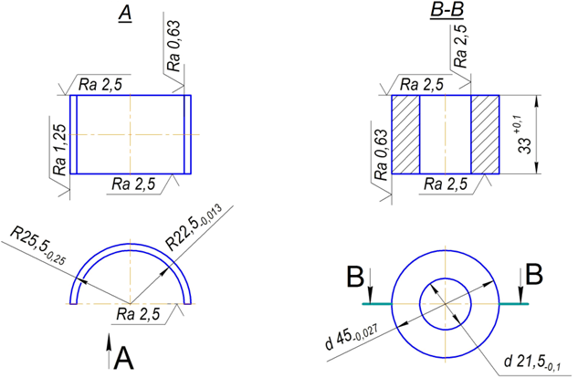
The contact diameter of the insert in the form of a thin-walled annular sleeve and the steel shaft was dMS = 45–0.027 mm, the insert thickness was s = 2.75 mm, the longitudinal width of both samples for the test chamber of the 2070 SMT-1 friction machine was B = 33+0.1 mm (Fig. 3). The contact area of the samples was 2 332 mm2. The load on the stationary sample was carried out using a special block to ensure sample rigidity and reliable tribocontact in the friction pair.
a b
Fig. 3. The general characteristics of the test samples: a – a stationary sample simulating a bearing shell;
b – a movable sample simulating a crankshaft journal
Before tribological testing, bases were applied to a stationary sample using an indenter using the Rockwell method. The angle of the apex of the diamond pyramid being inserted was 120°, the indenter was immersed to a depth of no more than 1.5 mm to reduce residual deformations on the surface near the depression being made (lifting the metal). These depressions were made in three places along the width of the block: in the center and at a distance of 5 mm on both sides from the central depression. The temperature in the friction zone was monitored using a data transmission system to a PC using a TPL 014-00 20/2n (TCC) thermocouple. Mechanical processing of stationary samples was carried out by grinding to a roughness of Ra = 0.63-0.70 μm, blocks – to Ra = 0.63-0.70 μm. The quality control of the treatment of the studied friction surfaces was carried out on a profilograph-profilometer 201. The samples prepared for testing were pre-run in for 90 minutes at a load of 2.5 MPa and a speed of 1.31 m/s.
The wear resistance criterion of the tested materials was the loss of mass, which was estimated by weighing on an analytical scale VLR-200 with an accuracy of 1∙10–4 g after each test cycle.
Before each test, the sample was impregnated with M-16G2CS oil at t = 150 °C for 2 hours, then washed in B70 gasoline (SS 1012-2013) and solvent No. 647, dried in an electric furnace at t = 120 °C for 10 minutes, followed by cooling to room temperature in air. After that, the samples were weighed and tested for wear resistance. At the end of the tests, the samples were weighed in a similar manner, excluding oil impregnation.
In this work, at all stages of tribological studies, each friction pair was tested at least three times in order to obtain objective and reliable results.
The results of the tribological tests performed are shown in Table 2.
Table 2
The results of tribological tests (weight wear of stationary samples h, g)
|
Additive concentration in lubricating oil, % |
Pressure, MPa |
||
|
0.1 |
0.4 |
0.7 |
|
|
0 |
0.039 |
0.045 |
0.063 |
|
1.0 |
0.038 |
0.042 |
0.055 |
|
2.0 |
0.037 |
0.041 |
0.053 |
The linear wear of the segment sample, m (linear wear values in µm are given in Table 3), was determined from the expression [13]:
hi = (Δmi / ρ) / A,
where Δmi – the mass of worn metal during the test cycle in the i-th test step, g; ρ = 2.83 ∙ 10–3 – the density of the material for the stationary sample, kg/m3; A = 2.332 ∙ 10–3 – the calculated area of the contour friction surface on the cylindrical segmental surface of the moving sample, m2.
Table 3
The linear wear of stationary samples h, µm
|
Additive concentration in lubricating oil, % |
Pressure, MPa |
||
|
0.1 |
0.4 |
0.7 |
|
|
0 |
0.00591 |
0.00682 |
0.00955 |
|
1.0 |
0.00576 |
0.00637 |
0.00834 |
|
2.0 |
0.00561 |
0.00622 |
0.00804 |
The wear intensity of the moving sample was calculated in the following way:
Ii = hi / SF,
where hi – the linear wear of the movable segmental sample, m; SF = 3 179.25 – the friction path during the test cycle, m.
The wear rate of the samples, μm/(103 · h), is calculated using the following expression (the calculation results are shown in Table 4):
Vi = (hi / 103) / T,
where hi – the linear wear, µm; T = 60 – the time of the tribological test stage, min.
Wear resistance is determined by the following expression:
Iv–1 = 1 / Vi. (1)
The results of calculation according to (1) are given in Table 5.
The visualization of the main results of tribological tests – wear, wear intensity and wear resistance of stationary samples – are presented in Fig. 4-6.
Table 4
The results of calculating the wear rate of stationary samples v, µm/(103·h)
|
Additive concentration in lubricating oil, % |
Pressure, MPa |
||
|
0.1 |
0.4 |
0.7 |
|
|
0 |
5.91 |
6.82 |
9.55 |
|
1.0 |
5.76 |
6.37 |
8.34 |
|
2.0 |
5.61 |
6.22 |
8.04 |
Table 5
The wear resistance of stationary samples, v–1
|
Additive concentration in lubricating oil, % |
Pressure, MPa |
||
|
0.1 |
0.4 |
0.7 |
|
|
0 |
0.1691 |
0.1465 |
0.1047 |
|
1.0 |
0.1735 |
0.157 |
0.1199 |
|
2.0 |
0.1782 |
0.1608 |
0.1244 |
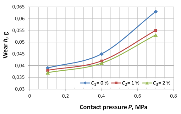
Fig. 4. The graphic dependence of wear of a stationary sample on the values of the volume concentration
of anti-wear additive in the lubricating oil and the contact pressure in the friction pair
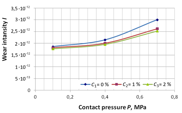
Fig. 5. The graphic dependence of the wear intensity of a stationary sample on the values of the volume concentration
of the anti-wear additive in the lubricating oil and the contact pressure in the friction pair

Fig. 6. The graphic dependence of wear resistance of a stationary sample on the values of volume concentration
of anti-wear additive in lubricating oil and contact pressure in the friction pair
The analysis of the results of the conducted studies showed a sufficiently high tribological efficiency of the developed lubricating composition “M-16G2СS oil + anti-wear additive”, since wear in the friction pair decreased by 5-15%, wear intensity decreased by 7-17%, and wear resistance increased by 6-18% depending on the concentration of the additive in the lubricating medium. Maximum wear of a stationary sample is typical for simulated pressures P = 0.7 MPa, which indirectly indicates a decrease in the thickness of the lubricating wedge between the crankshaft journal and the bearing shell to values in the range of 0.2-2 μm.
Conclusion
1. The friction and lubrication conditions of plain bearings in a marine diesel engine are considered. It is shown that under transient conditions, high loads or contamination of the lubricant used in plain bearings of marine diesel engines, the lubricating film becomes thin enough with a thickness in the range of 0.25-2.5 μm, and the local pressure is quite high – about 15-20 MPa.
2. It was revealed that for the operation of plain bearings in the hydrodynamic mode, the minimum pressure in the lubrication system is P = 0.05 MPa, otherwise, instead of a hydrodynamic wedge, a boundary friction zone is formed between the crankshaft journal and the liner. In this case, the permissible value of the criterion [pav] for bearings of the crank mechanism of a marine diesel engine is 12-18 (MPa·m)/s at an allowable pressure in the range [p] = 15-20 MPa.
3. A method for improving the tribological properties of lubricants and structural materials in sliding friction pairs by using a patented antiwear additive based on molybdenum diselenide MoSe2 and fatty acids has been considered and proposed. In this regard, the task of the scientific study has been completed – an assessment of the tribological characteristics of modified lubricants using the antiwear additive Nanoteks-12 has been carried out under conditions simulating the operation of a real plain bearing of the crankshaft of a 6ChNSP 18/22 marine diesel engine on a 2070 SMT-1 friction machine.
4. As a result of the calculation and experimental studies, graphical dependencies of wear, wear intensity and wear resistance of the simulated friction unit on the value of the volume concentration Ci of the antiwear additive in the lubricating oil and the contact pressure Pi have been obtained. It has been shown that the use of the additive in the M-16G2СS lubricating oil significantly improves its tribotechnical characteristics, since the wear of the friction pair is reduced by 5-15%, the wear intensity is reduced by 7-17%, and wear resistance is increased by 6-18% depending on the concentration of the additive in the lubricant.
1. Осипов О. В., Воробьев Б. Н. Судовые дизельные двигатели. СПб.: Лань, 2023. 356 с.
2. Чанчиков В. А., Гужвенко И. Н., Прямухина Н. В., Прямухина М. С., Ковалев О. П. Экспериментальное исследование трибологических характеристик смазочных масел со слоистыми модификаторами трения и возможности их применения в судовой технике // Вестн. Астрахан. гос. техн. ун-та. Сер.: Морская техника и технология. 2022. № 1. С. 22–34.
3. Чанчиков В. А., Гужвенко И. Н., Свекольников С. А., Бурмистрова О. В. Пути повышения надежности судовых дизельных двигателей // Судостроение. 2016. № 2. С. 27–30.
4. Пат. 2570643 Рос. Федерация, МПК С10М 169/04, С10М 125/22. Противоизносная присадка / Перекрес-тов А. П., Дроздов Ю. Н., Чанчиков В. А., Гужвенко И. Н., Свекольников С. А.; заявл. 22.07.2014; опубл. 10.12.2015, Бюл. № 34.
5. Дроздов Ю. Н., Юдин Е. Г., Белов А. И. Прикладная трибология (трение, износ, смазка) / под ред. Ю. Н. Дроз-дова. М.: Эко-Пресс, 2010. 604 с.
6. Возницкий И. В. Практические рекомендации по смазке судовых дизелей. СПб.: Моркнига, 2007. 128 с.
7. Ваншейдт В. А. Судовые двигатели внутреннего сгорания. Ленинград: Судостроение, 1977. 392 с.
8. Путинцев С. В. Механические потери в поршневых двигателях. Специальные главы конструирования расчета и испытаний. М.: Изд-во МГТУ им. Н. Э. Баумана, 2011. 288 с.
9. Бекмуродова О. А., Каратаев О. Р. Особенности расчета подшипников скольжения // Евраз. союз ученых. 2015. № 10 (19). С. 23–25.
10. Перекрестов А. П., Саламех А., Чанчиков В. А., Гужвенко И. Н., Абубакаров А. Я. Исследование эксплуатационных свойств противоизносных присадок для моторных смазочных масел в зависимости от процессов их обработки и седиментации // Науч. проблемы вод. трансп. 2020. № 64. С. 110–123.
11. Чанчиков В. А., Гужвенко И. Н., Перекрестов А. П., Прямухина Н. В., Павлов А. В. Повышение износостойкости узлов и деталей судовых ДВС путем модифицирования применяемых смазочных материалов // Мор. интеллектуал. технологии. 2019. № 4-2 (46). С. 59–68.
12. Справочник по триботехнике: в 3-х т. / под ред. М. Хебды, А. В. Чичинадзе. М.: Машиностроение, 1989. Т. 1. Теоретические основы. 400 с.
13. Трение, изнашивание и смазка: справ.: в 2-х т. / под ред. И. В. Крагельского, В. В. Алисина. М.: Машиностроение, 1979. Т. 2. 358 с.
14. Пат. 115917 Рос. Федерация, МПК G01N 3/56. Машина трения / Перекрестов А. П., Дроздов Ю. Н., Чанчиков В. А., Миронов В. Н.; заявл. 02.12.2011; опубл. 10.05.2012, Бюл. № 13.
15. ГОСТ 12337-2020. Масла моторные для дизельных двигателей. Технические условия. М.: Стандартинформ, 2020. 16 с.

