Россия
Россия
Россия
Россия
Россия
Россия
Рассматривается разработка системы подачи рабочей жидкости (моторного масла) для обеспечения подобия условий эксплуатации модели пружинного демпфера крутильных колебаний судового дизеля при экспериментах на лабораторном стенде испытательного центра Marine Technology Service ФГБОУ ВО «Астраханский государственный технический университет». В настоящее время пружинные (механические) демпферы крутильных колебаний судовых дизелей выпускаются только зарубежными фирмами. Для их проектирования, изготовления и эксплуатации необходима большая научная работа, включая проведение физического моделирования конструкции и условий эксплуатации лабораторных вариантов демпферов. Применение метода физического моделирования позволяет уменьшить затраты на испытания реальных пружинных демпферов крутильных колебаний судовых дизелей, определить основные зависимости параметров демпфирования от различных условий эксплуатации, выработать основные критерии безразборной диагностики для оценки его технического состояния и прогнозировать развитие аварийных ситуаций. Модернизация лабораторного стенда необходима для работы модельных пружинных демпферов с разработанной системой подачи рабочей жидкости. Распространение пружинных демпферов обосновывается особенностями конструкции таких устройств, позволяющей использовать как упругое, так и гидравлического демпфирование. Для разработки системы подачи рабочей жидкости были произведены расчеты жесткости и тепловой мощности модельного пружинного демпфера с учетом конструкции лабораторного стенда.
крутильные колебания, пружинный демпфер крутильных колебаний, физическое моделирование, система смазки пружинного демпфера, судовая энергетическая установка, судовой дизель
Introduction
To reduce tangential stresses in the elements of the shaft line from torsional vibrations to the norms of classification societies – the Russian Maritime Register of Shipping (RMRS) [1] and the Russian Classification Society [2] use a damper (damper), which is installed at the bow end of the diesel engine. Silicone dampers are installed in marine propulsion systems with a design scheme: “medium – speed diesel shaft line – fixed – pitch propeller”. But the design schemes of modern ships are becoming more complicated and include gearboxes, couplings, screw steering columns in the composition of the engine-propulsion complex, which affects the development of torsional vibrations both in amplitudes and in the number of resonant frequencies. Silicone dampers may be ineffective in this case, so elastic-friction dampers are used. If silicone dampers are designed and manufactured by the domestic industry, then more complex spring dampers are produced only by foreign manufacturers. In this case, two ways can be chosen for import substitution – reverse engineering of foreign-made spring dampers available on domestic ships or the development of own technologies for the design, operation and repair of such devices, with the training of specialized specialists. Obviously, the second way is strategically important with the development of our own technologies, therefore, to confirm theoretical research, a laboratory base is needed, including test benches made with maximum similarity to real ship devices and structures.
Setting the research task
On Wartsila 6L20 marine diesels [3], Geislinger torsional vibration dampers of the D60/14/2 or D60/16/2 models are most often used [4], which combine damping due to spring springs and hydraulic filler – engine oil supplied under pressure from the diesel lubrication system through the crankshaft in the damper cavity. The general view of the damper with spring springs and its design are shown in Fig. 1.
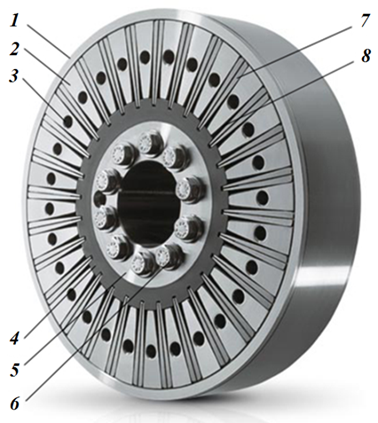
Fig. 1. Design of the torsional vibration damper Geislinger D60/14/2 [4]: 1 – external housing; 2 – flywheel sector;
3 – hole for fixing the flywheel with a lid;
4 – inner rim for fixing spring springs;
5 – flange for attaching the damper to the diesel crankshaft;
6 – bolts for attaching the damper to the diesel crankshaft;
7 – spring springs; 8 – cavities for oil passage
The design feature of this damper is the presence of a combined elastic and hydraulic part of the damping area (Fig. 2) – for this purpose, oil is supplied to the housing from the engine under pressure, as a result it is located between the packages of spring plates and converts vibrations into thermal energy, heating the oil [4]. This complicates the design of the damper, but allows you to use the advantages of both spring dampers and hydraulic dampers, as well as cool its structural elements.
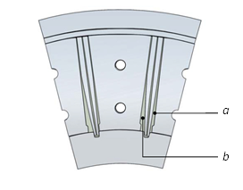
Fig. 2. Elastic and hydraulic damping in a spring damper [4]:
a – the oil cavity before the spring package;
b – the oil cavity after the spring package
For dampers with spring springs from Geislinger, an oil supply system is used, the operation scheme of which is shown in Fig. 3 [4].
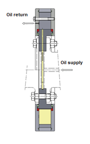
Fig. 3. The scheme of oil supply to the spring damper
of torsional vibrations [4]
Equipment and materials
The model spring damper is supposed to be used as part of the laboratory stand (Fig. 4) of the Marine Technology Service test center of the ASTU (MTS TC).
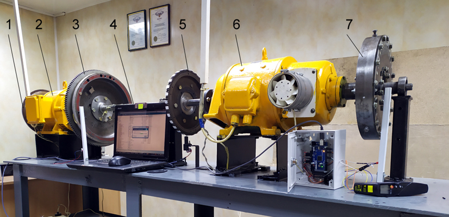
Fig. 4. General view of the laboratory stand of the MTS TC: 1 – small measuring gear No. 1;
2 – direct current generator; 3 – flywheel with a large measuring gear; 4 – shaft of the laboratory stand;
5 – small measuring gear No. 2; 6 – direct current electric motor; 7 – silicone torsional vibration damper
The laboratory stand simulates the operation of a marine engine and propulsion complex with a medium-speed diesel engine and direct transmission to the propeller. The direct current electric motor 6 simulates the operation of a marine internal combustion engine, with the possibility of creating a variable torque of variable amplitude and period of action. The presence of a long shaft 4 of small diameter and a large flywheel mass 3 models the design parameters of the ship's shaft line (high malleability and large flywheel mass). The direct current generator 2 simulates the operation of the propeller, with the possibility of changing the braking torque. The measurement of torsional vibrations is possible using two small flywheels with toothed rings 1 and 5 located at both ends of the laboratory stand, as well as one large measuring gear 3. The presence of a long shaft allows the measurement of tangential stresses using strain gauges.
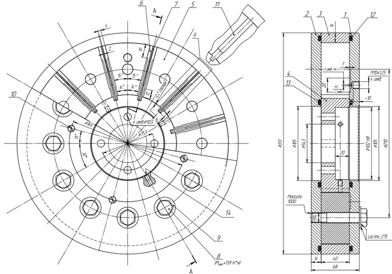
The model damper is planned to be manufactured on the basis of reverse engineering technology of the real Geislinger D60/14/2 damper available at MTS TC (Fig. 5), its drawing is shown in Fig. 6.
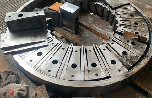
Fig. 5. Reverse engineering of the Geislinger D60/14/2 damper
a b
Fig. 6. Drawing of the general view of the model spring damper of torsional vibrations: а – front view; b – side view;
1 – side plate; 2 – flange; 3 – coupling ring; 4 – sprocket housing; 5 – intermediate block; 6 – plate spring; 7 – interplate spring;
8 – bolt M14 × 1.25; 9 – disc washer; 10 – bolt M10 × 1.25; 11 – insert; 12, 13 – sealing ring, 14 – lubrication oil supply
Next, a schematic diagram of the oil supply system to the model spring damper was developed and formed (Fig. 7).
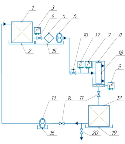
Fig. 7. Schematic diagram of the oil supply system
in a model spring damper of torsional vibrations:
1 – pressure tank; 2, 15, 16, 19 – oil leak pan;
3, 9 – oil temperature sensors at the inlet and outlet of the damper; 4, 11, 14 – taps; 5 – oil filter;
6 – oil pumping pump; 7 – pressure sensor;
8 – oil protection casing; 10 – oil flow control valve;
12 – oil drainage tank; 13 – oil pumping pump;
17 – flow meter; 18 – torsional vibration damper;
20 – drainage line to drain the oil
To calculate the thermal power, the Geislinger formula was used [4], according to which the thermal load in the Pkw, kW, damper for one harmonic order is calculated using the formula:
![]()
where i – the order of the harmonic oscillations; n – the rotation frequency, min–1; T – the vibration moment in the damper, N·m; CD – the stiffness of the damper, (N·m)/rad; kd – dimensionless damping coefficient.
According to the RMRS rules [1], when measuring torsional vibrations, it is necessary to consider the first 12 orders of harmonics.
The heat that is transferred to the circulating oil in the damper Poil, J, will be determined by the formula:
Рoil = сoilGoilΔtoil,
where сoil = 1 670 J/(kg·degrees) – the heat capacity of the oil; Goil – mass oil consumption, kg/h; Δtoil – oil temperature difference at the inlet and outlet of the damper, °C.
From here:
![]() (1)
(1)
or, when recalculating from kW to J, formula (1) is converted to the formula:

The excess oil pressure in the system must be at least:

where Р0 – atmospheric pressure, bar; Т = 15,4 N·m – the damping moment in the damper, equated to the vibration moment; Trel = 143 (N·m)/bar – the relative value of the damping moment selected from the catalog of Geislinger spring dampers [4] for a model of similar geometric dimensions.
Using the recommendations and methods of sources [5-7] in the MS Excel program, the necessary calculated data were obtained according to Tables 1, 2 and Fig. 7.
Table 1
Calculation of the parameters of the model torsional vibration damper
|
Parameter |
Value |
|
Number of spring packages, pcs. |
2 |
|
The number of plates in one spring package, pcs. |
2 |
|
The average thickness of the plate, m |
0.001 |
|
The width of the plate, m |
0.04 |
|
The working length of the plate, m |
0.079 |
|
The distance from the center to the place of sealing of the plate, m |
0.063 |
|
The modulus of elasticity of the plate material, N/mm2 |
2.059·105 |
|
The ductility of the calculated damper, rad/(N·m) |
0.001069291 |
|
The stiffness of the calculated damper, (N·m)/rad |
935.20 |
Table 2
Calculation of the parameters of the amplitude-frequency response of a model torsional vibration damper
|
Parameter |
Value |
|
Moment of inertia of the main oscillating system M, kg·m2 |
1.377 |
|
Stiffness of the main oscillating system K, (N·m)/rad |
7 454 |
|
Moment of inertia of the outer part of the damper m, kg·m2 |
0.1565 |
|
Stiffness of the spring part k, (N·m)/rad |
935 |
|
Disturbing force P0, kg |
15 |
|
The oscillation frequency of the main system w1, Hz |
73.575 |
|
Vibration frequency of the outer part of the damper w2, Hz |
77.29 |
|
Ratio of moments of inertia m/M, n |
0.114 |
|
Ratio of frequencies w2/w1, f |
1.05 |
|
Critical attenuation of oscillations Ck |
23.032 |
|
Static oscillation amplitude xst |
0.002012 |
|
Natural oscillation frequency without attenuation, Hz |
|
|
The frequency of the two-node waveform wc1 |
72.107 |
|
The frequency of the single-node waveform wc2 |
82.864 |
|
Frequency of forced oscillations w |
90.000 |
|
Relative oscillation frequency w/w1 |
1.223 |
|
Attenuation coefficient c |
5.095 |
|
Amplitude of mass fluctuations M, x11 |
0.00373 |
|
Dynamic gain factor x11/xst |
1.854 |
A stepwise change in the frequency of forced oscillations w and the calculation of the relative frequency of oscillations w/w1 allowed us to obtain data for plotting the amplitude-frequency response (Fig. 8) of the model damper with a characteristic increase in the dynamic gain coefficient to 5.1 with resonant oscillations, which are expected at a frequency of 0.87 (64 Hz) from the oscillation frequency of the system w1. The obtained dynamic gain coefficient corresponds to the range of its magnitude with effective operation of the damper according to the research of L. V. Efremov [8].
Based on the results of calculations and theoretical studies, the elements of the working fluid supply system to the model spring damper were determined: a consumable oil tank, an oil supply pump, an oil pumping pump from the bath, an oil filter, a drainage tank from the oil bath, an oil pressure sensor, an oil temperature sensor at the inlet to the damper, an oil temperature sensor at the outlet of the damper, oil temperature control unit, fittings and taps.
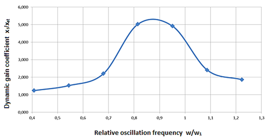
Fig. 8. Graph of the amplitude-frequency response of the model damper
For the operation of the damper, it is supposed to use Lukoil Navigo TPEO 30/40 oil [9], used for Wartsila 6L20, CAT engines, which include spring dampers of torsional vibrations.
The oil supply to the damper housing will be carried out through the shaft and flange of the damper attachment from the nose end of the laboratory stand. The design pressure, taking into account the hydraulic resistance of the damper, must be at least 3 bar.
The internal volume of the model damper is approximately 185 cm3, four inlet holes with a diameter of 4.9 mm are provided for lubrication of the inner surfaces of the damper, four holes with a diameter of 10 mm are provided for oil outlet in the lid. According to the calculation, the oil consumption for the operation of the model spring damper will be 32 kg/h, and the volume of the consumable oil tank will be 10 liters.
Conclusion
According to the conducted research, the following main conclusions can be drawn:
1. The spread of spring dampers is justified by the design features of such devices, which allows the use of both elastic and hydraulic damping.
2. The presence of a laboratory stand in the MTS TC allows for physical experiments with models of silicone torsional vibration dampers and for working with models of spring dampers, the system for supplying working fluid to the damper housing has been modernized.
3. According to the calculation, the oil consumption for the operation of the model spring damper will be 32 kg/h, the pressure, taking into account the hydraulic resistance of the damper, should be provided at least 3 bar.
1. Приложения к руководству по техническому наблюдению за судами в эксплуатации / Росс. мор. регистр судоходства. СПб.: Изд-во РМРС, 2022. 411 с.
2. Руководство Р.043-2016. Оценка работоспособности силиконовых демпферов крутильных колебаний судовых двигателей внутреннего сгорания / Росс. классификац. о-во. М.: Изд-во РКО, 2016. 66 с.
3. Руководство по эксплуатации двигателя Wartsila 6L20. 2013. 432 с.
4. Geislinger. Damper Catalog. Version 15.9. 2020. 50 p.
5. Родин П. Т. Диагностика демпферов // Судоходство. 1998. № 10. С. 70–71.
6. Родин П. Т. Эксплуатация силиконовых демпферов крутильных колебаний валопроводов судовых дизелей: учеб. пособие. М.: ЦРИА «Морфлот», 1980. 41 с.
7. Викулов С. В. Диагностика коленчатого вала судового дизеля по параметрам крутильных колебаний // Ползунов. вестн. 2013. № 4/3. С. 146–150.
8. Ефремов Л. В. Теория и практика исследования крутильных колебаний силовых установок с применением компьютерных технологий. СПб.: Наука, 2007. 276 с.
9. Масло Navigo TPEO 30/40. URL: http://www.fareastfish.ru/oil/trunk/navigo-tpeo-30-40.html (дата обращения: 22.04.2024).

