Россия
Астрахань, Россия
Россия
Россия
Приводятся результаты лабораторных исследований по безразборной оценке технического состояния модельного демпфера крутильных колебаний, проведенных в испытательном центре MTS ФГБОУ ВО «Астраханский государственный технической университет». Актуальность заключается в практическом применении полученных результатов исследования для безразборной оценки технического состояния силиконовых демпферов судовых дизелей и повышения эффективности существующей методики. Оценку предлагается осуществить при помощи глубокого анализа функции крутильных колебаний методами вейвлет-анализа и оконного преобразования Фурье для динамических режимов работы судовой энергетической установки с быстрым изменением частоты вращения валопровода – пуск, набор частоты вращения и остановка. Данные режимы могут быть опасны для судовых машинно-движительных комплексов, что подтверждается рядом фактов разрушения валов и потери гребных винтов при пуске и реверсе главной энергетической установки. В качестве критериев оценки технического состояния демпфера приняты как традиционные (величина напряжений в валах, амплитуда и частота крутильных колебаний), так и авторские (характер скалограмм вейвлет-анализа и оконного анализа Фурье) функции крутильных колебаний, а также величина вибрации по трем измерительным осям. Данные получены в результате использования в исследованиях авторских экспериментальных образцов системы мониторинга крутильных колебаний и измерительного устройства на базе акселерометров. В результате исследования установлена зависимость изменения напряжений в валах, частоты колебаний, вибрации и характера скалограмм вейвлет-анализа функции Морле и диаграмм оконного преобразования Фурье функции крутильных колебаний от трех смоделированных ситуаций технического состояния силиконового демпфера – при вытекании силикона, заклинке маховой массы и нормальной эксплуатации.
крутильные колебания, силиконовый демпфер, безразборная диагностика, техническое состояние, судовая энергетическая установка, судовой дизель
Introduction
The most dangerous situation for the development of torsional vibrations in marine propulsion systems is a decrease in efficiency or failure of the dampers of the main and auxiliary diesels. The failure of dampers can lead to an increase in torsional vibrations and fatigue failure of propeller and intermediate shafts, crankshafts of diesel engines, elastic coupling materials [1-3].
A non-selective technique for assessing the technical condition has been developed for silicone dampers [4, 5] and it involves measuring resonant stresses and torsional vibration frequencies, the values of which are compared with reference (calculated) values and norms, according to the rules of classification societies – the Russian Shipping Maritime Register (RSMR), the Russian Classification Society (RCS) and foreign ones. Thanks to this procedure, the residual life of the silicone damper can be predicted, however, the value of the assigned resource has a share of probability, which is indicated in the methodology and research of well-known specialists [4-10] and this is due, among other things, to a rather long period between control torsiographs – up to 15 000 hours. Also, in cases of high operating time of dampers – more than 60 000 hours, the accuracy of assessing their technical condition will be of great importance, therefore it makes sense to develop and apply additional criteria, for example, a deep analysis of torsiograms and the use of measurement of three-axis vibration in the nose of a diesel engine.
When assessing the technical condition, an analysis of the stresses and vibration frequency to which the silicone damper is initially configured is performed – that is, the parameters of the motor shape of torsional vibrations. The rules of the RSMR [4] indicate that for propulsive power plants having a shaft line and/or an elastic coupling of high malleability behind the engine flywheel (when their malleability is 10 or more times greater than the malleability of the crankshaft knee), the motor shape practically coincides with the single-node oscillation shape for the section of the rotating mass system “damper – crankshaft – flywheel” with the rest of the discarded part behind the flywheel of the internal combustion engine.
Recently, the method of constant (or periodic after short periods of time) monitoring of torsional vibrations has been considered for practical application, which allows measuring the actual values of voltages and signaling excess of permissible norms, as well as avoiding prolonged operation of the main power plant at dangerous resonant rotational frequencies. At the same time, there is a question of using torsional vibration monitoring systems to diagnose the technical condition of dampers. The complexity of the operational determination of the technical condition of the damper directly on board the vessel lies in the need for a detailed analysis of torsiograms and a number of calculations, including a harmonic analysis of the torsional vibration function using the Fourier transform. In this regard, the question arises about the development of criteria that can be determined quickly enough and taking into account the limited resources of the monitoring system to form a diagnosis of the technical condition of dampers based on the concept of “here and now”.
Setting the research task
The boundary conditions of the technical condition of the silicone damper are: complete freedom of rotation of the flywheel mass relative to the housing and fixing (locking) of the flywheel mass in the housing [6-11].
Complete freedom of rotation of the flywheel mass relative to the body occurs due to the leakage of silicone liquid from the damper due to non-tightness or damage to the structure. The suspension of the flywheel mass in the damper body occurs due to deformation of its elements or the transition of a silicone liquid into a gel substance with an increase in viscosity, for example, due to the accumulation of wear products from friction [6-11]. It is obvious that in this case there is a change in the total moment of inertia of the damper and, accordingly, a change in the parameters of torsional vibrations and stresses arising in the elements of the machine-propulsion complex.
In this study, the task was set to find out the possibility of indiscriminately determining the technical condition of a model silicone damper based on measurements made by experimental samples of a monitoring system [12] and a measuring device based on microelectromechanical accelerometers [13] by repeated experiments with controlled external influences (active experiment).
A model torsional vibration damper and a laboratory stand of the MTS Research Center of the FSBEI HE “ASTU” were used as the object of research [10, 14].
Physical experiment, methods of mathematical statistics for processing measurement results and wavelet analysis were used as research methods [15, 16].
Equipment and materials
The composition of the laboratory stand according to Fig. 1 includes (numbering of the elements of the stand begins with a damper to match the torsion scheme): 1 – torsional vibration damper; 2 – direct current electric motor; 3 – clutch No. 1; 4 – small flywheel No. 1; 5 – shaft; 6 – large flywheel; 7 – clutch No. 2; 8 – direct current generator; 9 – small flywheel No. 2. The laboratory stand simulates the operation of a marine engine and propulsion complex with a medium-speed diesel engine and direct transmission to a fixed-pitch propeller. The direct current electric motor 2 simulates the operation of a marine internal combustion engine with the possibility of creating a torque of variable amplitude and with a different period of action. The presence of a shaft 5 with a large length and small diameter and a large flywheel mass 6 provides high compliance and a large moment of inertia in the torsional circuit of the laboratory stand, respectively.

Fig. 1. General view of the laboratory stand MTS testing center
The direct current generator 8 simulates the operation of a propeller with the possibility of changing the magnitude of the braking torque. The measurement of torsional vibrations is possible using two small flywheels with toothed rings 4 and 9 located at both ends of the laboratory stand and one large measuring gear of the flywheel 6. The presence of a long shaft 4 and a large flywheel mass 6 allows stress measurement using strain gauges.
To measure the stresses in the shaft of the laboratory stand, an experimental sample of the monitoring system was used, which was developed at the Department of Operation of one Transport and Industrial Fishing of the FSBEI HE “ASTU” (Fig. 2). The metrological characteristics of the experimental sample of the monitoring system and measuring device based on microelectromechanical accelerometers were confirmed by comparative tests conducted on the reference equipment of the Federal State Budgetary Institution “The State Regional Center for Standardization, Metrology and Testing in the Astrakhan Region and the Republic of Kalmykia”.
According to Fig. 2: 1 – load cell (Wheatstone bridge with strain gauge resistors 2FKP5-400 manufactured by Sibtenzopribor); 2 – autonomous unit for measuring load cells; 3 – wireless charging of the battery of the autonomous unit; 4 – central measuring unit; 5 – shaft of the laboratory installation.
Before the measurements were carried out, the system was calibrated on a beam of equal displacement SM-25 and verified loads. The installation location of the strain gauge platform was determined as a result of calculating the laboratory stand for free torsional vibrations and analyzing elastic moments [6, 17].
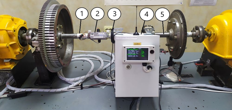
Fig. 2. General view of the experimental sample of the torsional vibration monitoring system
An experimental sample of a device based on microelectromechanical accelerometers was installed on the damper (Fig. 3). This made it possible to obtain the magnitude of vibration along three measuring axes and the angular amplitude of torsional vibrations.
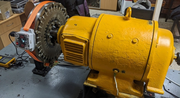
Fig. 3. A general view of the prototype of a torsional vibration measurement device based
on microelectromechanical accelerometers
Experimental results
A series of experiments was carried out – at least three repeated experiments for three states of the model torsional vibration damper:
1. Dry – without filling with silicone;
2. Stalled – with blocking of the flywheel mass;
3. Viscous – with filling the inner volume of the damper with silicone liquid PMS-4000.
To generate a sufficient amount of experimental data, measurements were carried out over several days with repeated modeling of the technical condition of the damper. The brand of silicone liquid PMS-4000 (with a viscosity value of 4000 cSt) was chosen based on the research of Doctor of Technical Sciences, Professor M. N. Pokusaev [10].
The operating mode of the laboratory stand was provided according to the program “start – set of rotation speed 375 rpm – stop”, but when processing the results it was necessary to take into account the errors that arose. For example, the results of stress measurements when filling a damper with silicone PMS-4000 and conducting an experiment at different durations, shown in Fig. 4, show the same trend, but the variation in the magnitude of stresses is in a certain range. In this case, using the maximum voltage in each of the cycles may give erroneous results. To improve the accuracy of the results, a statistical analysis of the obtained data was performed for their maximum correlation and further experiments with a short duration were carried out.
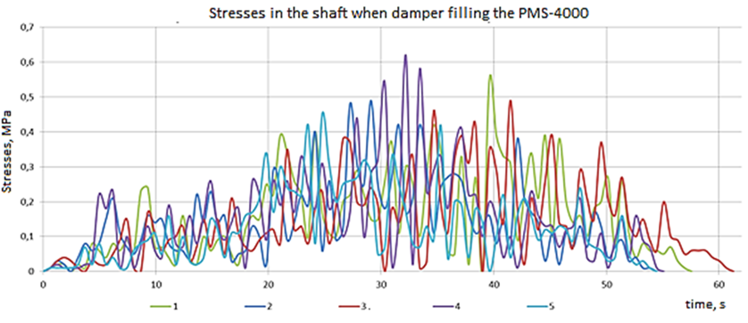
Fig. 4. The results of tension measurements in the shaft of the laboratory stand when filling
the damper with silicone PMS-4000
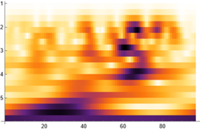
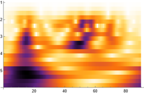
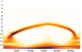
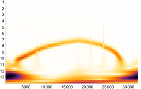
In addition to identifying identical dependences of stress development in the shaft of the laboratory stand and removing incorrect results, an analysis was carried out of the possibility of using traditional harmonic analysis using the Fourier transform in this case. Since the considered operating mode of the stand was accompanied by a rapid increase in the rotational frequency (within 30 s to 375 min–1) and a sharp change in torsional vibrations, it was decided to additionally use wavelet analysis with the Morlaix function, which is most suitable for analyzing torsional vibrations in such situations according to research [18, 19].
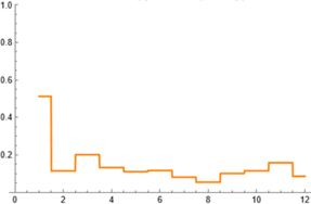
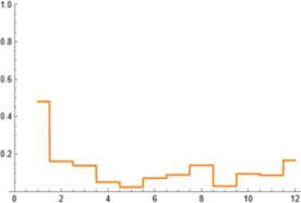
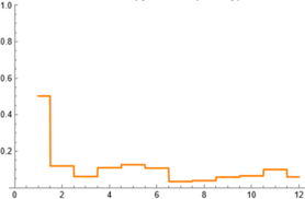
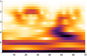
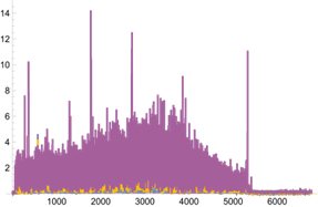
As a result of using the Wolfram Mathematica software product, scalograms were obtained, an example of which is shown in Fig. 5. Figure 6 shows the results of harmonic Fourier analysis to test the hypothesis of its limited use in this case.
|
a |
b |
c |
Fig. 5. Waveform analysis of the results of voltage measurements during filling
of the PMS-4000 model damper: a – 1st experience; b – 2nd experience; c – 3rd experience
|
a |
b |
c |
Fig. 6. Results of harmonic Fourier analysis when filling a model damper with silicone liquid:
a – 1st experience; b – 2nd experience; c – 3rd experience
As can be seen from Fig. 5, the scalograms obtained from the results of the 2nd and 3rd experiments are identical and differ from the sialogram of the 1st experiment. At the same time, Fig. 6 shows completely different results of harmonic analysis using the traditional Fourier transform for all three experiments. The noted high value of the amplitude of the 1st harmonic for all three experiments is a marker of the damper revolutions and does not characterize the development of torsional vibrations, i.e. it is a false harmonic caused by the beating of the damper body.
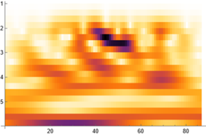
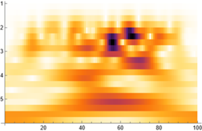
Due to the conducted wavelet analysis for experiments with three states of a silicone damper, the most identical experiments were identified and characteristic types of scalograms were obtained, shown in Fig. 7.
|
a |
b |
c |
Fig. 7. Scalograms of the wavelet analysis of the stress variation function in the shaft of the laboratory stand:
a – without silicone; b – the stalled flywheel mass; c – with silicone PMS-4000
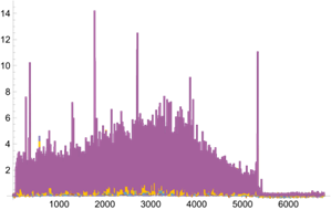
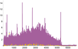
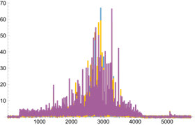
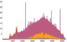
As can be seen from the data of the scalograms, when the damper is filled with silicone, the greatest response of the function with maximum stress amplitudes (colored purple) is observed in a fairly narrow section of the function, unlike graphs in the absence of silicone and a stalled flywheel mass. This characterizes the damping of the largest amplitudes with a silicone damper and the equalization of the response at an average level. Based on the results of the analysis, the most likely graphs of stress development in the shaft of the laboratory stand were obtained, depending on its technical condition (Fig. 8).
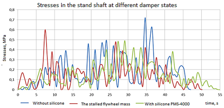
Fig. 8. Graphs of stress development in the shaft of the laboratory stand depending
on the technical condition of the damper
As can be seen from Fig. 8, the amplitudes and the nature of the stress development graphs differ depending on the technical condition of the damper. The analysis of the obtained tensograms was carried out according to two parameters: the maximum voltage occurring in the shaft and the average voltage in the cycle. Based on the results of averaging the stress values in three experiments for each state of the damper, Table 1 was obtained. The error in the magnitude of the stresses for each of the three series of experiments did not exceed 5%, which is a satisfactory convergence in experimental work.
Table 1
The results of the analysis of tensograms with changes in the technical condition of the model silicone damper
|
The condition |
Maximum stresses, MPa |
Change maximum stresses relative to the state with PMS-4000, % |
Average stresses, MPa |
The change in average stress relative to the state with PMS-4000, % |
|
With silicone PMS-4000 |
0.490 |
0 |
0.14 |
0 |
|
Without silicone |
0.705 |
+43.88 |
0.17 |
+21.43 |
|
The stalled flywheel mass |
0.595 |
+21.43 |
0.15 |
+7.14 |
As can be seen from Table 1, if we consider the full filling of cavities with silicone PMS-4000 as the normal technical condition of the damper, then in its absence there is an increase in maximum stresses by 43.9% and average stresses by 21.4%, which makes it possible to clearly identify the deterioration of the technical condition of the damper during operational measurements by the monitoring system. For the condition of a damper with a stalled flywheel mass, there is a not so significant increase in stresses – by 21.4%, and by 7.14% on average, which requires the use of additional criteria, for example, the frequency of torsional vibrations or conducting an in-depth analysis based on data transmitted to the technical service of the shipowner or the company servicing the monitoring system. In general, for a model damper and under the conditions of the experiment, it was found that the loss of silicone liquid in torsional vibration dampers is more dangerous than the loss of its flywheel mass. The authors suggest that the absence of silicone will lead to an increase not only in torsional vibrations, but also axial ones, as well as to the beating of the flywheel mass against the lid and possible damage to the damper housing. In the experiment with the absence of silicone, the authors observed periodic mechanical knocking, which may give another diagnostic sign of an unsatisfactory technical condition of a silicone or spring damper. This is an important conclusion, since the change in the magnitude and degree of danger of torsional vibrations during the operation of marine diesel engines is most often recommended to be assessed using purely subjective methods. These include increased noise, the appearance of knocks, increased vibration of the diesel engine and they can be ignored or even misinterpreted by ship mechanics. This leads to the need to implement torsional vibration monitoring using special systems that can generate alarms and issue diagnostic prescriptions for specific actions by a mechanic to avoid accidents.
Based on the results of measuring the magnitude of torsional vibrations using an experimental sample of a device based on microelectromechanical accelerometers and the use of the Wolfram Mathematica software product, the scalograms shown in Fig. 9 were obtained.
|
a |
b |
c |
Fig. 9. Waveform analysis of the accelerometer measurement results when filling the model damper with silicone:
a – 1st experience; b – 2nd experience; c – 3rd experience
The data of the scalogram on vibration measurements along the transverse X axis of the accelerometer (which characterize torsional vibrations) confirm the identity of the experiment, however, some deviations can also be noted, which are associated with errors in the conditions of the experiment and the processing of its results.
Figure 10 shows the results of the obtained torsional oscillation function using short-term (window) Fourier analysis (STFT), which differs from the traditional Fourier transform. The STFT method splits the signal into short sections (blocks) and applies the Fourier transform to each block, which allows analyzing the spectral characteristics of the signal at different points in time. This is applicable when the signal changes over time, for example, in non-stationary processes or in the case of temporary changes in the frequency components of the signal, as in this experiment. Such a conversion can be used in this case, since the sampling frequency of the signal by the device is quite high, the amount of data received per minute exceeds 25 000. The minimum sampling rate at which the adequacy of the Fourier transform is maintained is the subject of further research.
|
a |
b |
c |
Fig. 10. The results of a short-term Fourier analysis when filling a model damper with silicone:
a – 1st experience; b – 2nd experience; c – 3rd experience
Figure 10 shows the overlap of blocks of 10 values – 25 values each. Changing the sizes of blocks and overlaps also provide an understanding of the identity of the analyzed data. Thanks to the conducted Fourier window analysis for experiments with three states of a silicone damper, the graphs shown in Fig. 11 were obtained.
|
a |
b |
c |
Fig. 11. Typical scalograms of the wavelet analysis of the function of measuring angular displacements
of the damper body: a – without silicone; b – the stalled flywheel mass; c – with silicone PMS-4000
As a result, there was a significant decrease in amplitudes when using silicone liquid, as well as a change in the shape of the scalograms. Further, the authors calculated the dependences of the angular magnitude of torsional vibrations on the time of the experiment and on the rotation frequency.
Due to the conducted wavelet analysis for experiments with three states of the damper, the most identical and characteristic types of scalograms were identified and obtained, shown in Fig. 12.
|
a |
b |
c |
Fig. 12. Typical wavelet scalograms of the function of measuring angular displacements of the damper body:
a – without silicone; b – the stalled flywheel mass; c – with silicone PMS-4000
The scalograms indicate a change in the gradient, contrast, and density intensity when the technical condition of the damper changes. The data obtained confirm the identity of the results obtained using the monitoring system.
Based on the results of the experiment, graphs of the development of the amplitudes of torsional vibrations of the body of the model damper, depending on its technical condition, were obtained.
As can be seen from Fig. 13 the amplitudes and the nature of the graphs differ depending on the technical condition of the damper. The graphs were analyzed according to two parameters: maximum and average amplitudes (Table 2).
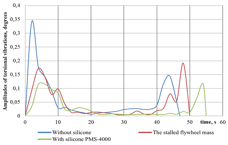
Fig. 13. Graphs of the development of torsional vibrations depending on the technical condition of the damper
Table 2
The amplitudes of torsional vibrations depending on the technical condition of the model silicone damper
|
The condition |
Maximum amplitudes of angular magnitudes, degrees |
Change in max. amplitudes relative |
Average values of amplitudes, degrees |
Changing environments. amplitudes relative |
|
With silicone PMS-4000 |
0.117 |
0 |
0.029 |
0 |
|
Without silicone |
0.342 |
+192.31 |
0.056 |
+93.10 |
|
The stalled flywheel mass |
0.192 |
+64.10 |
0.044 |
+51.72 |
Conclusion
As a result of the conducted research, the following main conclusions can be drawn and recommendations for further research can be made:
1. Torsional vibration monitoring systems can provide constant or periodic monitoring of stresses occurring in the elements of propulsion systems with the formation of alarms about exceeding permissible values, which will reduce the risks of accidents.
2. Degradation of silicone dampers leads to changes in maximum and average voltages, which can be used as criteria for assessing its technical condition in automated mode using a monitoring system and forming appropriate actions of ship mechanics – from switching to another operating mode and up to stopping the diesel engine.
3. With the loss of silicone fluid and emptying of the damper cavities, an increase in maximum stresses by 43.88% and average stresses by 21.43% is observed, which makes it possible to identify this change in the technical condition of the damper. At the same time, the increase in the maximum angular amplitudes of torsional vibrations on the damper body was 192%, and the average 93.1%.
4. With an increase in the viscosity of the silicone liquid up to the fixing of the flywheel mass with the body, the stress increase is not so significant and for maximum stresses is 21.43%, and the average is 7.14%, and clear identification in the operational measurement mode may be difficult. At the same time, the increase in the maximum angular amplitudes of torsional vibrations on the damper body was 64.1%, and the average 51.72%.
5. For a clearer identification of the state of the silicone damper of torsional vibrations, it is possible to develop a methodology for studying the scalograms obtained from the results of wavelet analysis, which requires conducting studies of torsiograms of real marine diesels with different operating hours of dampers and their technical condition. For this study, it is planned to use the experience and databases of the MTS Research Center, obtained since 2004.
6. The use of a device based on microelectromechanical accelerometers can provide an opportunity to assess the technical condition of the damper based on the results of wavelet analysis or short-term (window) Fourier analysis.
7. The reliability of the data obtained is confirmed by previously conducted studies obtained by the authors with the help of trusted equipment – the Astech Electronics strain gauge complex and the Ecophysics-110A spectrum analyzer vibrometer, which are used by specialists of the MTS Research Center of the FBSEI HE “ASTU” when carrying out real measurements on ships.
1. Final Report. Marine inquiry MO-2013-203 DEV Aratere, fracture of starboard propeller shaft resulting in loss of starboard propeller Cook Strait, 5 November 2013. Transport Accident Investigation Commission, 2016. 80 p.
2. Feese T., Hill C. Guidelines for preventing torsional Vibration Problems in reciprocating Machinery. Engineering Dynamics Incorporated, 2002. 48 p.
3. Худяков С. А. Вибростойкость и конструирование упругих систем судовых энергетических установок: автореф. дис. … д-ра техн. наук. Владивосток, 2015. 49 с.
4. Приложения к руководству по техническому наблюдению за судами в эксплуатации / Российский морской регистр судоходства. СПб.: Изд-во РМРС, 2022. 411 с.
5. Руководство Р.043-2016. Оценка работоспособности силиконовых демпферов крутильных колебаний судовых двигателей внутреннего сгорания / Рос. классификац. о-во. М.: Изд-во РКО, 2016. 66 с.
6. Ефремов Л. В. Теория и практика исследования крутильных колебаний силовых установок с применением компьютерных технологий. СПб.: Наука, 2007. 276 с.
7. Родин П. Т. Диагностика демпферов // Судоходство. 1998. № 10. С. 70–71.
8. Родин П. Т. Эксплуатация силиконовых демпферов крутильных колебаний валопроводов судовых дизелей: учеб. пособие. М.: ЦРИА «Морфлот», 1980. 41 с.
9. Викулов С. В. Диагностика коленчатого вала судового дизеля по параметрам крутильных колебаний // Ползунов. вестн. 2013. № 4/3. С. 146–150.
10. Покусаев М. Н. Демпфирование крутильных колебаний в валах судовых дизелей: моделирование, экспериментальные и натурные исследования: дис. … д-ра техн. наук. Астрахань, 2005. 346 с.
11. AVM Diesel. Sales & Service of Hasse & Wrede, 2015. 2 p.
12. Покусаев М. Н., Горбачев М. М. Результаты испытаний экспериментального образца системы мониторинга крутильных колебаний в судовых условиях // Материалы 67-й Междунар. науч. конф. Астрахан. гос. техн. ун-та (Астрахань, 29–31 мая 2023 г.). Астрахань: Изд-во АГТУ, 2023. С. 588–591. 1 CD-диск. URL: http://www.astu.org/Content/Page/5833 (дата обращения: 21.03.2024). № гос. регистрации 0322400207.
13. Горбачев М. М., Дьяченко А. В., Конищев Д. Г., Кокуев А. Г. Сравнительная оценка применения микроэлектромеханических акселерометров для измерения крутильных колебаний судовых машинно-движительных комплексов // Вестн. Астрахан. гос. техн. ун-та. Сер.: Морская техника и технология. 2024. № 1. С. 95–103.
14. Горбачев М. М., Покусаев М. Н., Сибряев К. О. Сравнительные испытания модельного демпфера крутильных колебаний при использовании различных видов наполнителей // Трансп. дело России. 2016. № 3. С. 102–104.
15. Абдель Р., Урожаев А. В. Исследование нестационарных динамических процессов при помощи вейвлет-анализа // Строит. механика и расчет сооружений. 2012. № 4. https://cyberleninka.ru/article/n/issledovanie-nestatsionarnyh-dinamicheskih-protsessov-pri-pomoschi-veyvlet-analiza/viewer (дата обращения: 26.03.2024).
16. Конышева В. Ю., Максимов Н. А., Шаронов А. В. Вейвлет-анализ в задачах контроля и диагностики линейных динамических систем // Тр. Моск. авиац. ин-та. URL: https://cyberleninka.ru/article/n/veyvlet-analiz-v-zadachah-kontrolya-i-diagnostiki-lineynyh-dinamicheskih-sistem/viewer (дата обращения: 20.03.2024).
17. Истомин П. А. Крутильные колебания в судовых ДВС. Л.: Судостроение, 1968. 303 с.
18. Глушков С. П., Глушков С. С., Кочергин В. И., Лебедев Б. О. Анализ динамических характеристик крутильно-колебательных систем судовых энергетических установок // Мор. интеллектуал. технологии. 2018. № 2 (40). С. 59–66.
19. Глушков С. П., Глушков С. С., Сигимов В. И. Вейвлет-функции Морлета в исследовании переменных составляющих крутящего момента двигателей внутреннего сгорания // Вестн. Сибир. гос. ун-та путей сообщения. 2016. № 2 (37). С. 45–51.

