


Россия
Россия
При параллельной работе дизель-генераторных установок в электротехнических комплексах морских судов фиксируется наличие обменных колебаний мощности. Обменные колебания мощности оказывают отрицательное воздействие на работу электрооборудования и систем автоматики морских судов. Результаты математического моделирования позволяют сделать вывод о целесообразности адаптивного изменения коэффициента передачи регуляторов частоты для уменьшения амплитуды обменных колебаний. Для исследования различных технологических режимов работы судовой электростанции с различным количеством параллельно работающих генераторов в математической модели задаются значения активных сопротивлений вместо генераторных автоматов, при этом большое значение активного сопротивления соответствует отключенному генератору, а малое значение активного сопротивления – генераторной установке, подключенной к главному распределительному щиту. Для проверки работоспособности и эффективности метода, основанного на изменении настроек регуляторов частоты, предложено провести компьютерное моделирование с динамической реализацией. Разработан метод определения компьютерной системой автоматического управления величины, характеризующей текущую амплитуду обменных колебаний мощности. Сделаны выводы о работоспособности метода устранения обменных колебаний мощности; результаты проверки метода, полученные с помощью разработанной компьютерной программы, позволяют рекомендовать внедрение блока устранения обменных колебаний мощности в системы управления электротехническими комплексами на морских судах.
обменные колебания мощности, параллельная работа, электротехнический комплекс, устойчивость, генераторный агрегат, настройки регулятора частоты
Introduction
Studies carried out at the operating power plants of sea vessels [1-3] with the joint parallel use of diesel generator sets confirmed the presence of power exchange oscillations (PEО).
To eliminate such processes, which extremely negatively affect the operation of the entire electrical power system of an autonomous object [4], a method has been developed based on varying the settings of the speed controllers of marine diesel generator sets [5, 6]. The development of the method was carried out in close connection with the sea vessel and the mathematical model of its ship electrical power system, while modeling the currents, voltages, moments, load angles and rotational speeds of the jointly used diesel generator sets of the studied vessel [5]. Given the values of the settings of the speed controllers, the current PEO amplitude was calculated from the results. The results of successive calculations confirmed a decrease in the amplitudes of exchange oscillations with a decrease in the gain of the speed controllers [5]. However, the behavior of the electrical power system remained unclear with an adaptive stepwise change in the settings of the speed controllers in dynamics [7]. According to the requirements of the international maritime convention on the safety of navigation Solas, it is not allowed to carry out any intervention that changes the configuration of the control system on an operating ship [8].
Taking into account the importance of confirming the operability, efficiency and safety of the proposed eliminating PEO method, it is necessary to test it before introducing it into the power plant control system of an operating sea vessel. Obviously, it is necessary to create a computer program based on a mathematical model that would demonstrate the operation of the PEO elimination unit in dynamics. And then after receiving positive results it will be possible to carry out tests on an operating ship.
Materials and methods of research
Figure 1 shows a diagram of a ship's multi-generator electrical power system, in which the generator circuit breakers are replaced by active resistances Rki. It is in such ship electrical systems that exchange power fluctuations are recorded (Fig. 2).
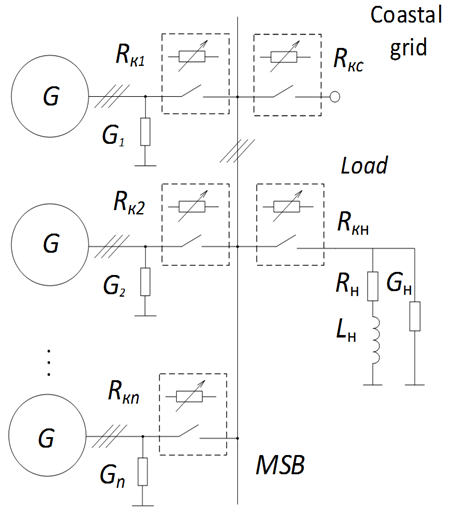
Fig. 1. Scheme of connecting generators
to the main switchboard
In a computer program, equations for the parallel operation of diesel generator sets are compiled, which include descriptions of the switches in the electrical circuits between the generators and the main switchboard [5].
If the generator works through the main switchboard to the grid, then the active resistance of the corresponding switch is close to zero, and in the case when the generator is not connected to the ship's grid, the active resistance of the switch tends to infinity. Thus, the mathematical description of the ship's electrical power system, which uses several diesel generator sets as sources of electricity, can be written in one system of equations. At the same time, the values of active resistances make it possible to conduct research when performing various technological operations by the ship's electrical power system, depending on the number of generators connected to the main switchboard.
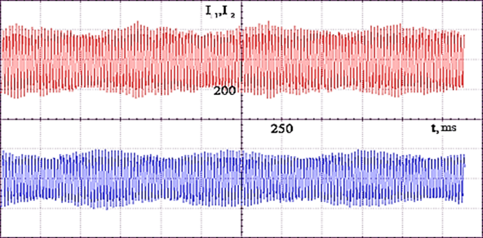
Fig. 2. Oscillograms of currents of two diesel generator sets connected in parallel
For a mathematical description of the generator stator circuits, the ship grid and the existing load, it is advisable to use a fixed coordinate system α, β. Using the design scheme for switching on generator sets shown in Fig. 3, we obtain the following equations:
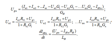
Iα1 = Igα1 + Ikα1; Iα2 = Igα2 + Ikα2; …Ikn = Igαn + Ikαn;
Uα1 = Ikα1Rk1 + Ugα; Uα2 = Ikα2Rk2 + Ugα; …Uαn =
= IkαnRkn + Ugα;
Igα1 = Uα1G1; Igα2 = Uα2G2; …Igαn = UαnGn;
IHα = IgHα + Ilα; IgHα = UgαGH; Ugα = IlHαRH + LH(dIlHα / dt),
where Gi is the conductivity; GH, RH, LH – ship grid load; Rki – generator breakers resistance.
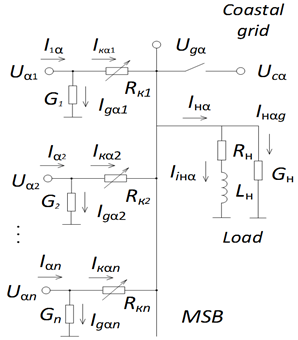
Fig. 3. Scheme of switching on generators for calculations
The solution of the system has the form:
Research results
Let us take as initial conditions for research the backlash of the speed controller of the first diesel generator Dn1 = 0.002, the backlash of the speed controller of the second diesel generator Dn2 = 0.01, the transmission coefficient of the speed controller of the first diesel generator Kω1 = 50, the transmission coefficient of the speed controller of the second diesel-generator Kω2 = 50, the commanded speed level of the first diesel generator ωr01 = 1, the commanded speed level of the second diesel generator ωr02 = 1. The presence of given backlashes determines the existence of power exchange oscillations, and the equality of the transmission coefficients and the settings of the speed controllers excludes the occurrence of power common-mode oscillations [5].
The results of calculations and construction with the above initial conditions presented in Fig. 4 confirm the existence of the PEO in the jointly parallel operation of two diesel generator sets with different backlash indicators in the speed controllers. The main feature is the correspondence of the maximum of the current envelope of the first generator to the minimum of the current envelope of the second generator. There are also oscillations in antiphase of the graphs of load angles and moments of these generators.
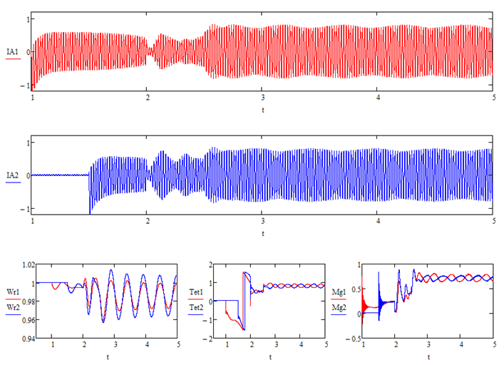
Fig. 4. Results of calculations and construction at Dn1 = 0.002; Dn2 = 0.01; Kω1 = 50; Kω2 = 50; ωr01 = 1; ωr02 = 1
When considering the results of such modeling, it is possible to determine the amplitude of exchange oscillations based on the scale on the coordinate axes. Then, depending on the obtained value of the oscillation amplitude, change the transmission coefficients of the speed controllers and repeat the simulation again with new data. Based on the results of repeated modeling, a conclusion is made about the effectiveness of changing the settings of the regulators and the need to continue such changes.
This approach has been a good tool in determining the causes of exchange and common-mode oscillations, as well as in developing methods and means that exclude such oscillations in a ship power plant. When using selective modeling, it is possible to choose any necessary values and analyze changes in oscillatory processes in the ship's electrical power system. Also, such a technique has proven itself well for constructing settings maps (Table) of the dependences of the characteristics of power exchange and power in-phase oscillations on the backlash values of the speed controllers of these regulators and other reasons, for example, shown in Fig. 5.
Dependence of the amplitude of power exchange oscillations on the values of time constants of speed controllers
|
Tω1 / Tω2 |
10 |
20 |
30 |
40 |
50 |
60 |
70 |
80 |
90 |
100 |
|
10 |
0 |
0 |
0 |
0.015 |
0.037 |
0.05 |
0.045 |
0.045 |
0.045 |
0.05 |
|
20 |
0 |
0 |
0.022 |
0.015 |
0.045 |
0.052 |
0.06 |
0.08 |
0.07 |
0.06 |
|
30 |
0 |
0.022 |
0.045 |
0.045 |
0.052 |
0.055 |
0.062 |
0.065 |
0.065 |
0.065 |
|
40 |
0 |
0.005 |
0.037 |
0.037 |
0.05 |
0.056 |
0.06 |
0.067 |
0.067 |
0.067 |
|
50 |
0.005 |
0.03 |
0.03 |
0.037 |
0.04 |
0.052 |
0.055 |
0.067 |
0.067 |
0.067 |
|
60 |
0.005 |
0.03 |
0.022 |
0.03 |
0.037 |
0.045 |
0.05 |
0.06 |
0.065 |
0.067 |
|
70 |
0.045 |
0.022 |
0.015 |
0.022 |
0.03 |
0.037 |
0.045 |
0.05 |
0.06 |
0.067 |
|
80 |
0.015 |
0.015 |
0.015 |
0.02 |
0.022 |
0.03 |
0.037 |
0.045 |
0.05 |
0.055 |
|
90 |
0.03 |
0.012 |
0.015 |
0.017 |
0.022 |
0.023 |
0.03 |
0.037 |
0.043 |
0.05 |
|
100 |
0.037 |
0.01 |
0.01 |
0.015 |
0.022 |
0.022 |
0.025 |
0.03 |
0.035 |
0.043 |
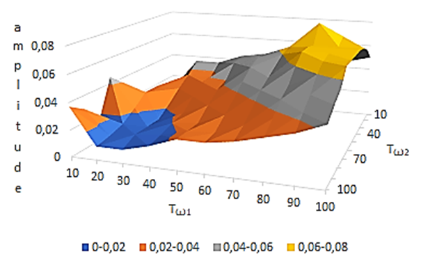
Fig. 5. Map of the dependence of the amplitude of the PEO on the values of the time constants of the speed controllers
Obviously, for the study of electrical power system, modeling with fixed values is the only acceptable approach. Of course, on an operating ship, the possibility of manual mode of changing parameters in automatic control systems is always provided. However, for regular operation, adaptive automatic tuning of the parameters of the speed controller is necessary. Therefore, in order to check the method for eliminating PEO, a computer program is needed that, after starting with given initial conditions, independently, without the participation of personnel, would determine the amplitude of the existing exchange oscillations and, if necessary, adaptively change the settings of the regulators of diesel generator sets. Such a computer program is the maximum approximation to the block of elimination of PEO for integration into the composition of the ship's electrical power system.
The key task on this path is the automatic determination of the amplitude of exchange oscillations. The following turned out to be quite effective from the point of view of simplicity, reliability and speed. First, it is necessary to construct the envelopes of currents I1 and I2 of generators operating in parallel and create digital arrays characterizing them. Next, the difference I1-I2 of the obtained envelopes is found both in graphical and digital forms. The envelopes and their difference represent a harmonically changing line, for example, a sinusoid. Moreover, the difference of the envelopes change symmetrically relative to the horizontal line, forming together the areas S1, S2, S3, etc. (Fig. 6).
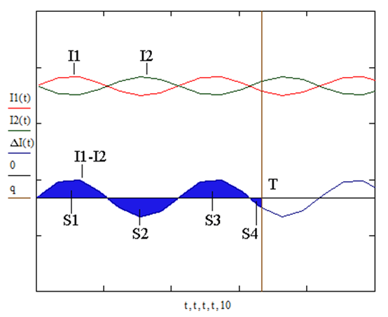
Fig. 6. Determination of the characteristic APEO of power exchange oscillations for two generators
It is necessary to determine the value of time T. Its value determines, on the one hand, the accuracy, and, on the other hand, the speed of the system. Sum of areas S1, S2, S3, etc. normalized by the time of their determination T, is a reliable indicator characterizing the PEO amplitude:
Depending on the requirements for the electrical power system in a specific mode of performing trip tasks, it is necessary to set in the program the permissible value of the PEO amplitude Aperm, with which the obtained APEO of the system is compared. The value of the permissible value Aperm is determined by the requirements of the electrical power system and may vary depending on the specific situation. To determine each of the areas S1, S2, S3, etc. the program sets the step along the abscissa-time axis. Depending on the given step, each figure with area S1, S2, S3, etc. is divided into a certain number of rectangles, the areas of which are found and summed up, forming the areas S1, S2, S3, etc., respectively. The assumption consists only in replacing one of the sides of each rectangle of the envelope section, formed by adjacent values of the change step along the abscissa-time axis. The number of summed areas of rectangles depends on the value of the step along the abscissa-time axis and also determines the accuracy and speed of calculations. Naturally, the speed of data processing depends on the characteristics of the computing system - processor, memory, etc.
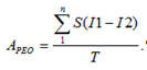
We present the result of the computer program (Fig. 7) for the initial conditions Dn1 = 0.002; Dn2 = 0.01; Kω1 = 50; Kω2 = 50; ωr01 = 1; ωr02 = 1. The program examines the time range from 3.5 to 5.5 seconds, so the normalization period of the envelope currents lasts for 2 seconds. On the graph, the current IA2 is shown in blue, and the envelope IA2max on it is red, and the current IA1 is shown in red with the blue envelope IA1max. The transmission coefficient Kω changes with a given step equal to 4, and the speed setting varies with a step of 0.01. The areal characteristic of power exchange oscillations, which estimates the amplitude level Aperm, is taken equal to 0.025.
Fig. 7. The results of the computer program at Dn1 = 0.002; Dn2 = 0.01; Kω1 = 50; Kω2 = 50; ωr01 = 1; ωr02 = 1
So, the program has made an adaptive dynamic change in the settings of the speed controllers of the diesel generator sets operating in parallel to eliminate the existing PEO. The effectiveness and efficiency of the measures and actions taken can be concluded by comparing the initial graphs in Fig. 2 and the final results presented in Fig. 7. It is obvious that in Fig. 7 there are practically no minimum and maximum of the envelope currents. Graphs of rotation frequencies, load angles and moments of diesel generator sets do not contain oscillatory sections in antiphase. While the program is running, the current values of the speed controller settings and the corresponding amplitude of exchange oscillations are displayed. Thus, the computer program is very flexible, it allows you to change the values of all current settings that specify both the initial parameters and the characteristics of the performance indicators of the electrical power system.
Conclusions
The computer program has demonstrated good efficiency and operability of the eliminating power exchange oscillations method in ship electrical power system with parallel operation of synchronous diesel generator sets. According to the results of the research, it is possible to recommend the use of a block for eliminating power exchange oscillations, which controls the settings of speed regulators, on the sea ships. In addition, the computer program that was used to test the performance of the method is a ready-made product for integration into the software systems of shipboard electrical power system.
1. Хватов О. С., Тарпанов И. А., Кузнецов П. В. Судовая электроэнергетическая система с обратимой валогенераторной установкой по схеме машины двойного питания и дизель-генератором переменной частоты вращения // Вестн. Астрахан. гос. техн. ун-та. Сер.: Морская техника и технология. 2021. № 3. С. 93-100.
2. Dar'enkov A. B., Samoyavchev I., Khvatov O. S., Sugakov V. Improving energy performance power station of ship with integrated electric propulsion // MATEC Web of Conferences. 2017. N. 108. P. 14002.
3. Sen'kov A. P., Dmitriev B. F., Kalmykov A. N., Tokarev L. N. Ship unified electric-power systems // Russian Electrical Engineering. 2017. N. 88 (5). P. 253-258.
4. Губанов Ю. А., Калинин И. М., Корнев А. С., Кузнецов В. И., Сеньков А. П. Направления совершенствования судовых единых электроэнергетических систем // Мор. интеллектуал. технологии. 2019. № 1-1 (43). С. 103-109.
5. Савенко А. Е., Голубев А. Н. Обменные колебания мощности в судовых электротехнических комплексах. Иваново: Изд-во ИГЭУ им. В. И. Ленина, 2016. 172 с.
6. Savenko A. E., Savenko P. S. Analysis of Power Oscillations Parameters in Autonomous Electrical Complexes Using the Method of Customization Charts Designing. Proceedings - 2020 International Ural Conference on Electrical Power Engineering, Uralcon 2020 (September 22-24, 2020). Institute of Electrical and Electronics Engineers Inc., 2020. P. 400-405.
7. Geertsma R. D., Visser K., Negenborn R. R. Adaptive pitch control for ships with diesel mechanical and hybrid propulsion // Applied energy. 2018. V. 228. P. 2490-2509. DOI:https://doi.org/10.1016/j.apenergy.2018.07.080.
8. Авдеев Б. А. Интеллектуальные энергоэффективные системы морских судов // Вестн. Керч. гос. мор. технолог. ун-та. 2021. № 4. С. 99-113.
