


Россия
Россия
Проводится исследование потери напора при движении кипящего двухфазного потока в вертикальных и наклонных трубах испарителей судовых холодильных установок. Изучение восходящего двухфазного потока перспективно с точки зрения практического применения. Подобное движение характерно для различных видов промышленного теплообменного оборудования, в том числе для разработки перспективных видов испарителей, например вертикальных аппаратов для судов, в которых происходит внутритрубное кипение хладагента. Разработана методика и поставлен эксперимент для исследования процессов в парогенерирующих каналах холодильных установок под различными углами наклона с фиксированной высотой. При этом изменялась длина канала, что позволило проанализировать потери на трение. Применен новый подход, максимально приближающий модель к действительному процессу кипения с учетом постоянного возрастания пара в канале. Проведены экспериментальные исследования и выявлены данные по потерям напора при изменении угла наклонна парогенерирующего канала. Представлены основные зависимости и различные компоненты гидросопротивлений при движении кипящего двухфазного потока. На основании полученных данных доказана оправданность перехода судовых испарителей холодильных установок к вертикальному расположению теплообменного парогенерирующего пучка. Полученные результаты свидетельствуют о том, что увеличение наклона трубы при условии сохранения высоты приводит к увеличению потерь напора. Определена примени-мость к судовым холодильным машинам – переход к вертикальным аппаратам имеет достоинства, прежде всего по снижению потерь напора. Полученная совокупность данных позволяет рекомендовать конструкции вертикальных испарителей для вспомогательных судовых установок.
гидросопротивления, двухфазный поток, испаритель, наклонные трубы, холодильная техника
Introduction
The movement of a boiling stream in a vertical and inclined pipe is a special case when a two-phase flow flows inside pipes and channels and has a number of features. First of all, this is due to the influence of the hydrostatic liquid column which is small in a horizontal channel [1].
The study of the ascending two-phase flow is promising from the point of view of practical application. The upward movement is typical both for heat engineering, in particular, in steam generating boilers and for refrigeration engineering for the development of promising types of evaporators, for example, vertical apparatus for ships, in which the refrigerant boils inside the pipes [2].
The vertical shell-and-tube evaporator has a better distribution of the refrigerant along the boiling channels compared to the horizontal one. This is due to the supply of refrigerant coming from the bottom cover, it is evenly distributed over all tubes of the bundle because the liquid refrigerant does not move from its axis of motion under the action of gravitational force and does not change its direction as it happens in a horizontal evaporator when rotated in the back cover. The upper tubes of a horizontal evaporator have a lower heat transfer coefficient due to the uneven distribution of the refrigerant; after turning, the upper part of the tube bundle is less filled with liquid and part of the heat exchange surface remains dry, which reduces the efficiency of the device. In the vertical evaporator this problem is solved due to the uniform filling of the tubes. The liquid supplied from below into the vertical tube bundle is better distributed, which makes it possible to increase the heat transfer coefficient due to the wettability of the entire tube area.
An important issue in the design of steam generators with vertical and inclined pipes is the study of pressure losses during the movement of a two-phase flow in these pipes. An experiment was carried out to determine the influence of an inclined pipe on the hydrodynamics of a two-phase flow.
The purpose of this work is to study the parameters of a boiling two-phase flow during its movement in vertical and inclined pipes of a ship evaporator of a refrigeration machine.
The relevance of the work lies in obtaining data on the hydraulic resistance of a two-phase boiling flow in pipes and channels of different directions while maintaining a constant height of the steam generator.
Scientific novelty consists in the study of hydraulic resistance in different slopes pipes during the movement of a boiling two-phase flow.
Experiment method
To compare the designs of heat exchangers, an experiment was conducted to compare pressure losses in vertical and inclined pipes. The experiment was carried out with the height of the experimental pipe unchanged in order to exclude the effect of hydrostatic pressure and to show how the hydraulic resistance changes with inclination.
For the experiment, a stand was developed (Fig. 1).
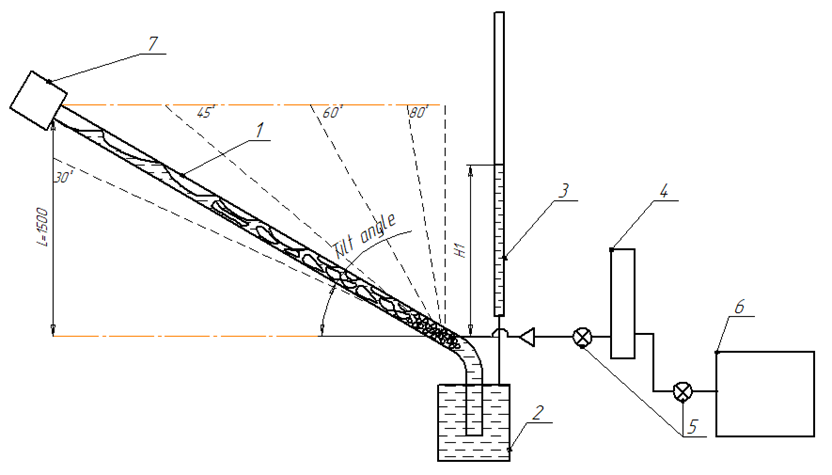
Fig. 1. Experimental stand: 1 – experimental pipe; 2 – tank; 3 – measuring pipe; 4 – air collector; 5 – control valves;
6 – compressor; 7 – funnel
The experiment was carried out for a pipe with a diameter d = 14 mm and a height L = 1.5 m:
− length 3 (angle of inclination − 30o);
− length 2.1 (angle of inclination − 45o);
− length 1.7 (angle of inclination − 60o);
− length 1.6 (angle of inclination − 80o);
– vertical pipe.
The experiment was carried out as follows.
The stand was filled with water through the level-holding tank, then air was supplied down the experimental pipe from the compressor through the air collector, corresponding to the calculation of the heat load of the evaporator q = 1 kW/m2. The supply was carried out in such a way that there was no splash into the funnel from the experimental tube when completely wetted. Then the liquid level in the measuring tube H1 was measured and the total head loss was calculated ΔP = ρ'gH1 (where ρ' is the density of the liquid, g is the free fall acceleration, H1 is the liquid level in the measuring tube). At the next stage, the air flow was increased sequentially until the heat load corresponded to q = 5 kW/m2, and the level measurements in the measured pipe and calculations were carried out.
The calculation of the volume of air supplied to the experimental tube was taken in accordance with the regeneration in the heat exchange channel of the evaporator, depending on various heat flows.
For example, the heat flow corresponding to q = 1 kW/m2 was calculated based on the main parameters of the channel (for example, a pipe 1.5 m long and 14 mm in diameter), such as the heat exchange surface of the pipe − f = 0.066 m2, the heat of vaporization − r = 270 kJ/kg (for R410a freon at a boiling pressure of 1 bar).
Volumetric steam flow, m3/s:
![]() (1)
(1)
where ρ″ – density of vaporous freon.
Hydro resistance
An important parameter of the hydrodynamics of a two-phase flow is the pressure loss in the channel.
The total pressure difference between two sections of the channel is the sum of the differences necessary to overcome the leveling pressure ∆plev, friction loss ∆pfr, local resistance ∆plr, as well as losses lost on the acceleration of the liquid and vapor phases ∆pac:
Δp = Δplev + Δpfr + Δplr + Δpac.
The data in [2] showed that the main component of the hydraulic resistance in a vertical pipe is the leveling head. This conclusion comes from the values obtained during the calculation of each of the main resistance components.
The determining factor for calculating the pressure loss is the mass flow rate ωρ, kg/(m2 · s), when moving in the pipe, which is equal to the mass of the refrigerant supplied per unit area of the pipe section per second, set through the amount of gas supplied to the stand through the formula (1):
ωρ = qf / rS,
where S is the cross-sectional area of the pipe, m2.
An important parameter of a two-phase flow is the true vapor content showing what part of the pipe section is occupied by steam.
Then the leveling head:
![]()
where l is the height of the two-phase flow, m.
Pressure loss due to friction of a two-phase flow [2]:
![]() (2)
(2)
where ξ – friction coefficient; ψ – flow coefficient; x – mass vapor content; ω0 – circulation velocity, m/s;
ω0 = ωρ / ρ'.
In [3], another form of the formula for calculating ∆рfr is presented:
![]()
where ψfr – coefficient takes into account the influence of the flow.
Head loss to overcome local resistance for a two-phase flow according to [1-3]:
![]()
where ξlr – coefficients of local resistance are taken according to [4].
The head loss due to acceleration is calculated as the difference in the amount of motion between the considered sections of the channel. Head loss due to acceleration according to [5-7]:
Δрac = (ρ'ω0)2(y2 – y1),
where ![]() y1 – section at the beginning of the pipe; y2 – section at the end of the pipe.
y1 – section at the beginning of the pipe; y2 – section at the end of the pipe.
When deviating from the vertical position, friction losses increase according to formula (2); experimental studies were carried out to prove this statement [8-10].
Influence of inclination on head loss in a pipe
Figure 2 shows graphs of the dependence of pressure losses in pipes on gas flow.
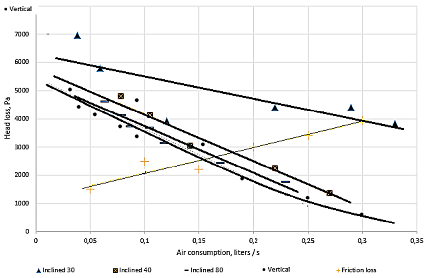
Fig. 2. Head loss when gas is supplied through the lower section into vertical and inclined pipes;
pipe diameter – 14 mm; height – 1.5 m
It can be seen from the graph that with air flow increase through a pipe with liquid pressure losses decreased, this is due to a decrease in the density of a two-phase flow.
The results of the experiment show that with an increase in the angle of deviation from the vertical position losses in the pipe increase due to an increase in the length and, as a result, friction losses. In addition, regimes characteristic of a horizontal channel arose in inclined pipes, i.e. a stratified regime was observed at the end section. This fact is the main difference between hydrodynamics in the case of two-phase flow in inclined pipes and in vertical ones. The wave mode leads to the fact that the upper part of the pipe remains unwetted, and therefore, when the flow boils, the end section has a lower heat transfer coefficient. Therefore, from the point of view of heat transfer, the use of vertical channels is more advantageous for the purpose of wetting the wall at the end section.
The difference in head loss in vertical and inclined pipes, while maintaining its height, is friction loss, since other types of losses do not change. With an increase in inclination while maintaining the height, the length of the pipe increases and it leads to friction losses increase. It can be seen from the experiment that the losses increase with the length of the pipe at a given flow rate. Moreover, the experimental and calculated data differ significantly. So the existing calculation models need to be refined.
Further research
To study the structure of a two-phase flow, further studies will use the method of dynamic light scattering applied to bubbles. For this, coherent radiation with a wavelength of 625 nm and a system of mirrors are used. The whole method is based on the polarization of the light beam on ascending bubbles and the detection of residual radiation, which, it is assumed, will allow us to investigate the size and fluctuations of groups of bubbles, as well as the vapor content in the pipe section.
In addition, thermal effects are studied, primarily in the heat transfer coefficient, in order to complete the picture of the thermohydrodynamics of a boiling two-phase flow at low temperatures during upward motion in a vertical pipe.
Conclusions
An experimental study of vertical and inclined pipes has shown that friction losses due to heat flows used in refrigeration engineering make up a significant part of the total pressure loss. As applied to marine refrigeration machines, it can be said that the transition to vertical evaporators has its advantages, primarily in terms of reducing friction pressure losses.
The study showed that increasing the slope of the pipe, while maintaining the same height, leads to an increase in head loss. And, therefore, when the height of the steam generator is 1.5 meter, the vertical arrangement of the steam generating channels is preferable.
Analyzing the experiments carried out, we can say that the pressure loss in the studied inclined pipes is in the range from 0.5 to 7 thousand Pa.
It should be especially noted that in the transition from inclined pipes to vertical ones, the hydrodynamics of the flow also changes, which also has its advantages, primarily related to better wettability of the heat exchange surface and, as a result, an increase in the efficiency of the heat exchange equipment of the ship installation, due to an increase in the heat transfer coefficient between wall and boiling refrigerant.
1. Букин В. Г., Кузьмин А. Ю., Минеев Ю. В. Обобщение экспериментальных данных по гидродинамике и теп-лообмену при течении двухфазных потоков внутри труб // Вестн. Астрахан. гос. техн. ун-та. 2006. № 6 (35). С. 108-115.
2. Кутепов А. М., Стерман Л. С., Стюшин Н. Г. Гидродинамика и теплообмен при парообразовании. М.: Высш. шк., 1986. 447 с.
3. Данилова Г. Н., Богданов С. Н., Иванов О. П. и др. Теплообменные аппараты холодильных установок. Л.: Машиностроение, 1986. 303 с.
4. Идельчик И. Е. Справочник по гидравлическим сопротивлениям. М.: Кн. по требованию, 2012. 557 с.
5. Малышев А. А., Киссер К. В., Зайцев А. В. Истинные параметры кипящих хладагентов в трубках и каналах // Вестн. Междунар. акад. холода. 2017. № 2. С. 53-56.
6. Ейдеюс А. И., Никишин М. Ю., Кошылев С. В. Потери давления на трение при кипении хладагента в трубах // Вестн. Междунар. акад. холода. 2014. № 1. С. 64-67.
7. Bukin V. G., Kuzmin A. Y., Mineev Y. V. Generalization of experimental data on a heat transfer and a flow friction at boiling of mixture ozonefriendly refrigerating agent R407C in a horizontal pipe with twisted tabulators // Science and Tech-nology. 2006. N. 4. P. 69-73.
8. Niezgoda-Zelasko B., Zelasko J. Refrigerant boiling at low heat flux in vertical tubes with heat transfer enhancing fitting // International Journal of Refrigeration. 2015. V. 54. P. 151-169.
9. Изюмченко Д. В., Николаев О. В., Шулепин С. А. Газожидкостные потоки в вертикальных трубах: парадоксы гидродинамики // Вести газовой науки. 2013. Т. 4. С. 36-45.
10. Изюмченко Д. В., Стоноженко И. В., Гужов К. Н., Сулейманов В. А., Бузинова О. В., Николаев О. В. Сравни-тельный анализ результатов экспериментальных исследований вертикальных газожидкостных потоков и расчетов по программе OLGA // Вести газовой науки. 2016. № 2 (26). С. 234-255.
