Россия
Россия
Россия
Россия
Россия
Рассматривается влияние эффективности регенерации разработанной противоизносной присадки на триботехнические свойства смазочной композиции, включающей смазочное масло и данную присадку. В качестве противоизносной присадки выступал слоистый модификатор трения – диселенид молибдена MoSe2, перемешанный в объеме композиции ненасыщенных жирных кислот – стеариновой и олеиновой. В качестве базового смазочного материала выбрано смазочное масло М-16Г2ЦС, относительно которого ведется сравнение триботехнических свойств других смазочных материалов, представленных для испытаний. Для всех циклов испытаний использовался объем не более 25 см3 смазочного материала во избежание высокой тепловой инерции при движении испытуемых образцов на машине трения. Выполнены эксперименты по регенерации присадки на установке ротационного перемешивания авторской конструкции, при этом раствор имеет длительный срок хранения – 8 640 ч (около 12 календарных месяцев). Выявлена возможность восстановления равномерного распределения диселенида молибдена по объему присадки во взвешенном состоянии. Данная смазочная композиция после восстановления структуры перемешиванием может использоваться в изготовлении смазочной композиции на основе масла М-16Г2ЦС. С использованием возвратно-поступательного узла трения машины трения, имитирующего цилиндропоршневую группу судового дизеля, полученная смазочная композиция сравнивалась с рядом смазочных материалов на основе диселенида молибдена, растворы присадок которых до внесения в смазочное масло имеют различные сроки хранения, а также с базовым смазочным маслом. Произведена оценка триботехнических свойств смазочных материалов на основе базового масла М-16Г2ЦС методом определения весового износа и дальнейшим использованием этой величины для оценки ре-сурса узла трения. Ротационная регенерация показала удовлетворительную эффективность в частичном вос-становлении триботехнических свойств смазочной композиции с участием присадки, но недостаточно эффек-тивна по сравнению с ротационно-пульсационным перемешиванием присадки в целях создания перспективных смазочных композиций.
смазочный материал, противоизносная присадка, регенерация присадки, машина трения, триботехнические испытания, поршневое кольцо, цилиндр, срок хранения
Introduction
Long-term storage of lubricants for a period of several weeks to several months predetermines the deterioration of their lubricating properties, associated primarily with tribotechnical efficiency and oxidation [1-5]. When using motor lubricating oils, their long-term storage can occur in several cases: preliminary storage of oils before using on a ship, idle time of the ship without operation of ship mechanisms and lubrication systems. In both cases, lubricating oil can exhibit deterioration in both tribological and oxidative properties over a long period of storage. For modern marine lubricating oils, a decrease in these properties can occur, among other things, due to precipitation or general degradation of the additive package included in their composition. In particular, additives with solid layered friction modifiers are susceptible to sedimentation phenomena. In the author's researches of the tribological properties of marine oils, this is stated in works [6-9] using the example of the use of anti-wear additives based on molybdenum diselenide.
These sources convincingly show for an additive [10], that the preliminary storage period of more than 36-48 hours before being added to the lubricating oil determines the tribotechnical efficiency of the resulting lubricating composition. Thus, in source [6], the authors revealed a significant precipitation of the solid component of the additive - molybdenum diselenide MoSe2 during a storage period of 36-512 hours. It follows that the priority possibility of restoring the tribological properties of a lubricating composition based on a combination of circulating lubricating oil and an additive containing molybdenum diselenide is the periodic regeneration of the additive during its long the storage period (more than 36 hours). This problem is addressed in this research by technological measures and tribological tests of lubricants containing the additives [10].
A purpose and objectives of the research
The purpose of the research is an evaluation of the tribological properties of a lubricant composition (LC), including a regenerated (with tribological and rheological characteristics restored by rotary mixing) solution of the anti-wear additive in comparison with LC, in which the additive solution has undergone long-term storage, short-term storage, and with lubricating oil, on the basis of which LSs are produced.
The objectives of the research:
1) an implementation of measures to regenerate the anti-wear additive solution [10] during the designated time period (the additive solution stored for more than 8 640 hours or 1 440 days);
2) a realization of tribological tests of various lubricants, including:
– the base lubricating oil for marine using;
– LC based on the base lubricating oil and the anti-wear additive [10], containing the layered friction modifier – molybdenum diselenide MoSe2 with the storage period of the lubricant composition of no more than T = 24 hours;
– LC based on the base oil and the additive [10] with a preliminary storage period of the additive added to the oil, T = 8 640 hours;
– LC based on the base oil and the additive [10], with the storage period of the additive T = 8 640 hours, when regenerating the additive solution before adding it to the lubricating oil by rotary mixing for a time T = 2 hours;
3) an assessment of the tribological properties of lubricants by measuring the weight wear of test samples of the friction machine.
Conditions and the technology of carrying out the tribological tests
Four types of lubricants were prepared for tribological tests (Table 1). Three lubricants were “oil + additive” lubricating compositions, and the fourth lubricant was base lubricating oil M-16G2TSS (SS 12337-2020).
The lubricating oil M-16G2TSS is a base lubricant against which the tribological properties of other lubricants prepared for testing are compared. For each of the four test cycles, a volume of at least 25 cm3 of lubricant is used to avoid high thermal inertia when the test samples are moving.
Table 1
The lubricants for tribological tests
|
Cycle |
The lubricant |
Conditions for preparation for testing |
|
1 |
The circulating oil M-16G2TSS (SS 12337-2020) [11] |
The base lubricating oil |
|
2 |
LC “lubricating oil M-16G2TSS + anti-wear additive” |
Holding the LC in a closed container for |
|
3 |
LC “lubricating oil M-16G2TSS + anti-wear additive”, including the anti-wear additive restored by stirring |
The preliminary regeneration of the additive (storage period T = 8 640 hours) before adding to the LC by stirring for T = 2 hours |
|
4 |
LC “lubricating oil M-16G2TSS + anti-wear additive”, which has storage and oxidation |
Keeping the additive in a closed container for T = 8 640 hours before adding it to the lubricating oil and producing the LC |
The anti-wear additive was a layered friction modifier, molybdenum diselenide MoSe2, mixed in the volume of a composition of the unsaturated fatty acids – stearic and oleic [10]. The main feature of MoSe2 is the possibility of precipitation in the form of a solid phase during some storage time of the additive solution, exceeding 36-48 hours [6], because its density exceeds the density of a set of the stabilizing unsaturated acids. In all cases of producing the lubricating compositions using molybdenum diselenide (LCs No. 2 - No. 4), the concentration of the additive by volume of the base lubricating oil was C = 1.0%.
The technology of carrying out the tribological tests and preparatory measures for them are shown in Fig. 1
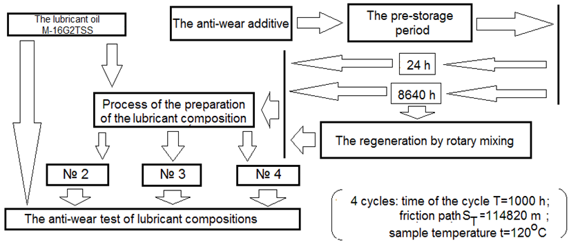
Fig. 1. The technological measures for the conducting tribological tests
The technical description of the machine for the regeneration of the anti-wear additive
The anti-wear additive is regenerated (is restored by the uniform distribution of particles of the solid phase component in the solution) on a special rotary machine, the drawing of which is shown in Fig. 2.
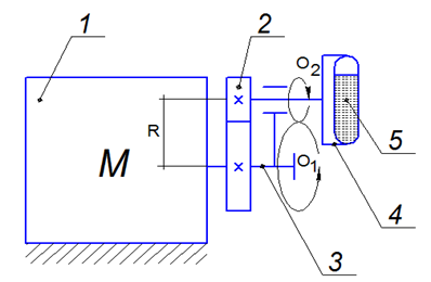
Fig. 2. The drawing of the machine for the regeneration
of the additive: 1 – an electric motor; 2 – a gear wheel;
3 – a crank; 4 – a holder; 5 – a vessel
The electric motor 1 drives the crank 3, the shaft of which contains a pressed gear of gear 2. At the end of the crank there is a hole for placing a roller, one of the ends of which is occupied by the counter gear wheel 2, the second is occupied by holder 4, in which vessel 5 for the regenerated solution of the additives is clamped. So, the crank 3 is a planetary carrier, which runs the small gear of the gear wheel 2 around the large one. It promotes the double law of rotational motion of the vessel 5 in its holder – movement along the radius R of a large circle by the shaft of motor 1 around the O1 axis with an angular velocity ω1 and rotational motion with a speed ω2 relative to the O2 axis of the roller with the counter gear. The angular velocities are related by the relation ω2 = 2.5ω1. The main goal of this combination of mutual rotational movements of the vessel with the additive solution is to uniformly mix its components in the volume of the solution.
The main characteristics of the machine are shown in Table 2.
Table 2
The main technical characteristics of the installation for regeneration of anti-wear additive
|
Parameters |
Meaning |
|
The angular speed of the rotation of the electric motor shaft ω1, s–1 |
150.7 |
|
The angular speed of the rotation of the crank shaft ω2, s–1 |
376.75 |
|
The radius of the circle of the rotation of the vessel holder around the shaft axis R1, m |
0.032 |
|
The radius of the circle of rotation around the crank shaft R2, m |
0.02 |
|
Drive motor power N, kW |
0.65 |
|
Volume of the vessel with the regenerated liquid V, l |
0.5 |
|
Maximum of the continuous regeneration time T, h |
2 |
General pictures of the additive solutions for test cycles No. 2, 3 according to Table 1 are shown in Fig. 3. Solution No. 2 was obtained after a storage period of the additive T = 8 640 hours, solution No. 3 – after a storage period of no more than T = 24 hours, solution No. 1 – regenerated by stirring for 2 hours after a storage period of T = 8 640 hours. The letter designations A, B and C refer, respectively, to a significant, moderate and a weak zone of solution separation when molybdenum diselenide precipitates in the additive solution. The solution No. 3, shown in Fig. 3, did not undergo structural separation due to precipitation of molybdenum diselenide during the storage period T = 24 hours.
The additive solution [10] with the storage period of T = 8 640 hours (about 12 months) was subjected to the regeneration. During this time, the additive solution acquired a color shade that was significantly lighter (solution No. 1 in Fig. 3) than the original solution (No. 3 in Fig. 3), in which molybdenum diselenide was uniformly suspended. It indicates for a large mass of the layered friction modifier that precipitated by gravity during the specified storage period.
The additive solution, which had undergone long-term storage in a volume of 450 cm3, was placed in the mixing vessel of the rotary machine with the filling hole carefully sealed. During the period T = 2 hours, the machine imparted a rotational movement to the vessel around the O1 axis in a circle with the radius of R = 0.032 m, while the vessel rotated around the O2 external axis at a speed to 2.5 times greater than the machine’s electric motor shaft. The uniform mixing of the additive solution was ensured; at the end of the mixing, the uniformity and saturation of the color shade of the solution was assessed. It was established that the shade of the solution obtained by stirring (No. 2 in Fig. 3) in the lower part of a 10 cm3 volumetric tube is almost the same as the additive solution stored for no more than 24 hours (solution No. 3 in Fig. 3). That is a uniform regeneration of the distribution of molybdenum diselenide by volume of solution in suspension was carried out. The successful regeneration of the solution according to the structure with using the described machine is achieved due to high centrifugal forces, combined in action by the forces arising around the main drive shaft and the planetary roller, which acts as the axis of rotation of the vessel holder.
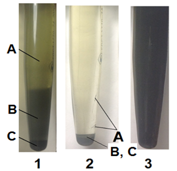
Fig. 3. The color pictures of the additive solutions for the different storage periods (No. 2 and No. 3) and the
regeneration by stirring (No. 1): A – the part of the solution with a significant degree of stratification of the solution
due to the precipitation of molybdenum diselenide in the additive; B – part of the solution with a moderate degree
of stratification of the solution due to precipitation
of molybdenum diselenide in the additive;
С – part of the solution with a weak degree
of stratification of the solution when molybdenum
diselenide precipitates in the additive
The technical description of the friction machine for the tribotechnical tests and the technology for their implementation
A reciprocating type friction machine is shown schematically in Fig. 4. The electric motor 1 of an asynchronous type with a power of N = 0.8 kW drives a worm gearbox 2 through a flange coupling. The gearbox has two outputs of rotational motion, one of which ends in the crank shaft 3, and the other drives a counter 9 for the straight path traveled by the crank 3. The rotating crank has a radius of 36.8 mm and activates the connecting rod 4, which has a hinged connection with the piston 5. The piston 5, moving along the stationary cylinder 6, carries two segments of the piston ring 7, expanded by the spring 8. The rear end of the piston has a smooth rod with a guide for its precise translation movement without significant deviations in the radial direction, that is, towards the cylinder wall. Cylinder 6 is a test cylinder, that is, experiencing friction from the piston ring segments. It is fixed without the possibility of an axial mobility in a steel cylinder of the machine, fixed to its frame. The piston 5, in conjunction with the cylinder 6, forms a gap, while the segments of the ring 7, under the action of the spring 8, which opens them, are tightly pressed against the cylinder. In accordance with this, a “ring-cylinder” friction pair is formed, with the ring imitating a ring segment made of gray alloy cast iron with nodular graphite (SS 3443-77) [12], and the cylinder sleeve imitating a stationary cylinder made of gray cast iron with flake graphite (SS 1412-79) [13]. The surface roughness dimensions of the ring segment and the fixed cylinder correspond to Ra1.25/Ra0.63, and it corresponds to the roughness parameters of real marine diesel parts with a diameter of the cylinder of D = 160-450 mm according to SS 7133-80 and SS 7274-80 [14, 15]. During the tests, cylinder 6 is heated to a temperature of t = 120 °C by an external heating element. The decompression force of the spring 8 is F = 300 ± 3 N, it corresponds to the accepted dimensions of the contact area of the segment of the piston ring 7, amounts to a contact pressure on the surface of the cylinder 6 equal to P = 1 ± 0.01 MPa. The spring is compressed until the coils touch in the corpus of the piston 5. To prevent significant expansion of the coils, exceeding the amount of linear wear of the segment of the ring or the cylinder, special stops are inserted under the ends of the spring, exerting pressure on the segments of the ring. This measure was needed for an eliminating a large error in changing the load on the segment of the ring, despite the fact that the load on the stationary sample must remain constant.
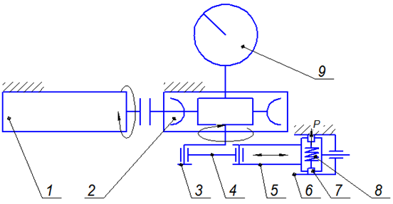
Fig. 4. The drawing of the reciprocating friction machine: 1 – an electric motor; 2 – a worm gearbox; 3 – a crank shaft;
4 – a connecting rod; 5 – a piston; 6 – a stationary cylinder; 7 – a segment of the piston ring; 8 – a spring; 9 – a path counter
Each segment of the ring is a subject to measurement of the weight wear (in each test, the value of weight wear of two segments is summed up and displayed as the arithmetic average) and the cylinder.
The main characteristics of the friction machine during tribological tests are given in Table 3. The scale factor in the tests is taken with a multiplicity of k = 10 based on the ratio of the actual diameter of the bushing in the marine internal combustion engine and the diameter of the cylinder used in the machine.
Table 3
The main technical characteristics of the friction machine
|
Parameters |
Meaning |
|
The main spring load F, N |
300 ± 3 |
|
The contact pressure on the surface of the segment of the ring Р, MPa |
1 ± 0,01 |
|
Number of double strokes of the piston per hour of operation n |
1 560 |
|
The continuous operation time per test cycle T, h |
1 000 |
|
The friction path per test cycle ST, m |
114 820 |
|
The diameter of the tested cylinder D, m |
0.037 |
|
The thickness of the ring segment in axial direction B, m |
0.007 |
|
The contact area of the ring segment A, m2 |
2.97 · 10–4 |
|
The outer diameter of the spring Dv, mm |
26.3 |
|
The diameter of the spring coil dv, mm |
2.7 |
|
The spring height unloaded/fully compressed N, mm |
16.4/5.4 |
|
The spring index i |
9.75 |
|
Number of the spring turns z |
2+0,5 |
The tribological tests of the lubricants listed in Table 1 are carried out as follows:
1) for each test cycle, three test samples are provided: two cast iron segments of the piston ring installed oppositely on the movable piston and one cast iron removable cylinder placed in the main cylinder of the machine; samples are fixed in their regular locations;
2) the liquid lubricant is poured into the main cylinder of the machine in accordance with the test cycle (according to Table 1) in an amount of at least 25 cm3;
3) the movable unit of the machine in the form of a crank shaft, a connecting rod and a movable piston in its guide is set in motion, which is maintained at the same speed of a rotation of the crank shaft n = 26 rpm during the time interval T = 1 000 hours or the friction path made by the samples of ST = 114 820 m;
4) after the specified time and passing the friction path controlled has been overcome by the counter, the moving unit of the machine stops, the test cylinder is removed from the main cylinder, and the test segments of the ring are removed from the piston;
5) the test samples are cleaned of lubricant residues and wear products, after which their weight wear should be assessed on scales with a measurement accuracy of 0.001 g.
The calculation of the resource values of the simulated friction unit
The resource value of a friction unit is calculated by the following expressions:
1) the linear wear of a segment sample, m
hi = (mi / ρ) / A, (1)
where mi – the mass of a worn metal during the test cycle, g; ρ = 7.87 ∙ 106 – the density of cast iron for segment-type samples, g/m3; A = 2.97 ∙ 10–4 – the area of the contour friction surface on the cylindrical segmental surface of the movable sample, m2;
2) the wear rate of the segment sample
Ii = hi / ST, (2)
where ST = 114 820 – the friction path during the test cycle, m;
3) the wear rate of the segment sample, µm/h
Vi = hi ∙ 106 / Тc, (3)
where Tc = 1 000 – the time of the test cycle, h;
4) the resource of the friction unit based on the maximum gap between real parts (the “ring-cylinder” pair of a marine diesel engine), h
Ti = hmax / Vi, (4)
where hmax = 200 – the maximum gap that satisfies the normal (failure-free) operating conditions of the “ring-cylinder” friction pair (based on ring wear) of a conventional marine diesel engine, μm; Vi – the wear rate of the segment sample, μm/h [16].
The results of the tribological tests
The main results of the research of tribological properties are given in Tables 4 and 5. The estimated indicators of the tribological properties of the ring segment and cylinder at each test cycle are:
– the linear wear of the sample surface hi, m;
– the wear rate Ii;
– the wear rate of the samples Vi, µm/h;
– the residual resource Ri, h, of a real “ring-cylinder” pair along the gap.
Table 4
The main tribological indicators for the cylinder
|
Cycle |
The lubricant |
mi, g |
hi, m |
Ii |
Vi, µm/h |
Тi, h |
|
1 |
The base oil M-16G2TSS |
0.042 |
1.797 · 10–5 |
1.565 · 10–10 |
0.018 |
11 130.43 |
|
2 |
The manufactured LC |
0.038 |
1.626 · 10–5 |
1.416 · 10–10 |
0.016 |
12 302.06 |
|
3 |
The restored LC |
0.048 |
2.054 · 10–5 |
1.789 · 10–10 |
0.021 |
9 739.13 |
|
4 |
The long-term stored LC |
0.061 |
2.61 · 10–5 |
2.273 · 10–10 |
0.026 |
7 663.58 |
Table 5
The main tribotechnical indicators for the ring segment (arithmetic average of the wear values of two segments)
|
Cycle |
The lubricant |
mi, g |
hi, m |
Ii |
Vi, µm/h |
Тi, h |
|
1 |
The base oil M-16G2TSS |
0.045 |
1.925 · 10–5 |
1.677 · 10–10 |
0.019 |
10 388.4 |
|
2 |
The manufactured LC |
0.041 |
1.754 · 10–5 |
1.528 · 10–10 |
0.018 |
11 401.9 |
|
3 |
The restored LC |
0.052 |
2.225 · 10–5 |
1.938 · 10–10 |
0.022 |
8 989.96 |
|
4 |
The long-term stored LC |
0.067 |
2.866 · 10–5 |
2.497 · 10–10 |
0.029 |
6 977.28 |
Figure 5 shows a comparative diagram (separately for cylindrical and segmented samples) of changes of the value of the linear wear h for the lubricants in test cycles No. 1-4.
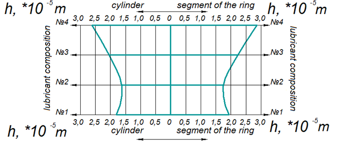
Fig. 5. The comparative diagram of changes of the linear wear h in test cycles No. 1-4
Table 6 shows a comparison of the lubricants in terms of tribological properties (the amount of the wear of the samples) with each other (the lubricants are located horizontally in the Table 6, in relation to which the tribological properties of the lubricants located vertically are compared).
Table 6
The comparison of the wear h of the samples in the lubricant tests – increase in wear, %*
|
The lubricant |
The base oil |
Restored LC |
Long-term stored LC |
|
Freshly prepared LC |
11 |
26 |
61 |
|
10 |
27 |
63 |
|
|
Base oil |
14 |
45 |
|
|
16 |
49 |
||
|
Restored LC |
27 |
||
|
29 |
|||
* The numerator gives data for the cylinder, the denominator – for the ring segments.
The tribological characteristics of the lubricant composition No. 4 (according to Table 1) are significantly lower (by 27-63%) compared to other lubricant compositions (No. 2 and 3), as well as the base lubricating oil M-16G2TSS, which is explained by the long storage period of the additive before adding oil and the corresponding precipitation of molybdenum diselenide in its volume (a very small part of it from the initial solution can take part in the formation of a protective layer on the surface of the test samples lubricated with the resulting LC No. 4). The tribological properties of LC No. 2 with the participation of an additive solution regenerated by two-hour rotational stirring after a storage period of T = 8 640 hours are significantly higher than LC No. 4 with an additive solution with a long storage period (27-29%), but lower by 10-11% than that of LC No. 1, which had a storage period of no more than 24 hours, which indicates incomplete recovery of the mass of the molybdenum diselenide from the precipitate in the solution before its addition to the base lubricating oil.
Based on the results of the tribotechnical research, the base lubricating oil M-16G2TSS showed an intermediate position: better by 45-49% in relation to LC No. 4 for long-term storage due to the loss of a significant mass of molybdenum diselenide in this LC in the sediment of the preliminary solution, but worse by 14-16%, than that of LC No. 2 with a pre-regenerated additive solution.
Conclusion
1. The technological measures were made to regenerate the additive [10], which has a storage period of 8 640 hours; positive results of regeneration were revealed, namely, the possibility of restoring the uniform distribution of molybdenum diselenide throughout the volume of the additive solution in the suspension.
2. The lubricating compositions “oil + additive based on molybdenum diselenide” were prepared and its tribotechnical efficiency was tested on the reciprocating friction machine simulating the cylinder-piston group of a marine diesel engine.
3. The assessment of the tribological properties of lubricants based on M-16G2TSS oil using the weight wear method and further arithmetic transformations of it into the resource of the friction unit showed that for long-term stored oil with the additive [10], when it is regenerated by rotary mixing, it is possible to increase the tribological properties in comparison with lubricating ones oils equipped with the anti-wear additive with molybdenum diselenide and having a long storage period.
4. The rotational regeneration shows satisfactory efficiency in partially restoring the tribological properties of a lubricant composition with an adding of the additive [10], but is not effective enough compared to rotational pulsation mixing of the additive solution in order to create perspective anti-wear LCs.
1. Возницкий И. В. Практические рекомендации по смазке судовых дизелей. СПб.: Моркнига, 2007. 128 с.
2. Путинцев С. В. Механические потери в поршневых двигателях. Специальные главы конструирования расчета и испытаний. М.: Изд-во МГТУ им. Н. Э. Баумана, 2011. 288 с.
3. Дроздов Ю. Н., Юдин Е. Г., Белов А. И. Прикладная трибология (трение, износ, смазка). М.: Эко-Пресс, 2010. 604 с.
4. Справочник по триботехнике: в 3-х т. / под ред. М. Хебды, А. В. Чичинадзе. М.: Машиностроение, 1989. Т. 1. Теоретические основы. 400 с.
5. Трение, изнашивание и смазка: справ.: в 2-х т. / под ред. И. В. Крагельского и В. В. Алисина. М.: Машинострое-ние, 1979. Т. 2. 358 с.
6. Перекрестов А. П., Саламех А., Чанчиков В. А., Гужвенко И. Н., Абубакаров А. Я. Исследование эксплуата-ционных свойств противоизносных присадок для моторных смазочных масел в зависимости от процессов их обработки и седиментации // Науч. проблемы вод. трансп. 2020. № 64. С. 110-123.
7. Чанчиков В. А., Гужвенко И. Н., Андреев А. И., Шулимова М. А., Свекольников С. А. Исследование и разра-ботка перспективных смазочных материалов для применения в судовых дизельных двигателях и повышения ресурса цилиндропоршневой группы двигателя внутреннего сгорания // Вестн. Астрахан. гос. техн. ун-та. Сер.: Морская техника и технология. 2021. № 4. С. 62-74.
8. Чанчиков В. А., Гужвенко И. Н., Прямухина Н. В., Прямухина М. С., Ковалев О. П. Экспериментальное исследование трибологических характеристик смазочных масел со слоистыми модификаторами трения и возможности их применения в судовой технике // Вестн. Астрахан. гос. техн. ун-та. Сер.: Морская техника и технология. 2022. № 1. С. 22-34.
9. Чанчиков В. А., Гужвенко И. Н., Прямухина Н. В., Прямухина М. С., Ковалев О. П. Экспериментальное исследование ресурса цилиндропоршневой группы судовых двигателей внутреннего сгорания при использовании различных смазочных композиций // Вестн. Астрахан. гос. техн. ун-та. Сер.: Морская техника и технология. 2022. № 3. С. 69-76.
10. Пат. 2570643 Рос. Федерация, МПК С10М 169/04, С10М 125/22. Противоизносная присадка / Перекрестов А. П., Дроздов Ю. Н., Чанчиков В. А., Гужвенко И. Н., Свекольников С. А.; заявл. 22.07.2014; опубл. 10.12.2015, Бюл. № 34.
11. ГОСТ 12337-2020. Масла моторные для дизельных двигателей. Технические условия. М.: Стандартинформ, 2020. 16 с.
12. ГОСТ 3443-77. Отливки из чугуна с различной формой графита. Методы определения структуры. М.: Изд-во стандартов, 1977. 10 с.
13. ГОСТ 1412-79. Чугун с пластичным графитом для отливок. Марки. URL: https://studfile.net/preview/9679966/page:14/ (дата обращения: 28.08.2023).
14. ГОСТ 7133-80. Дизели судовые, тепловозные, промышленные и газовые двигатели. Кольца поршневые. Общие технические условия. М.: Изд-во стандартов, 1980. 6 с.
15. ГОСТ 7274-80. Дизели и газовые двигатели. Втулки цилиндров чугунные. М.: Изд-во стандартов, 1980. 9 с.
16. Хромов В. Н. О восстановлении деталей судовых дизелей термопластическим деформированием // Судостро-ение. 2016. № 2. С. 50-54.

