


сотрудник
Калининград, Калининградская область, Россия
Калининград, Калининградская область, Россия
Калининград, Калининградская область, Россия
Балтийск, Калининградская область, Россия
Результаты анализа аварийной статистики свидетельствуют о том, что проблема повышения безопасности мореплавания остается весьма актуальной. При этом одной из причин возникновения серьезных повреждений корпусов судов является действие интенсивных локально распределенных нагрузок, приводящих нередко к разрушению конструкций и даже гибели судов. Перспективным путем решения указанной проблемы является внедрение в практику эксплуатации судов бортовых интеллектуальных систем. Для разработки блока контроля местной прочности необходимо располагать методами расчета элементов конструкций за пределом упругости, обеспечивающими требуемую точность при минимальных затратах вычислительных мощностей. Разработана методика, позволяющая учитывать влияние просадки смежных с нагружаемым шпангоутов на деформирование локально загруженного бортового перекрытия, и проведена оценка возможности ее применения в блоке контроля местной прочности бортовой интеллектуальной системы. Представленная методика основана на реализации гипотезы «о мгновенном раскрытии пластических шарниров». Проведено сопоставление с результатами расчета по методу конечного элемента, реализованного в программном пакете ANSYS. Отмечено приемлемое для прочностных расчетов судовых корпусных конструкций согласование результатов, что свидетельствует о возможности практического использования разработанной методики, в частности при реализации блока контроля местной прочности в бортовых интеллектуальных системах.
бортовые интеллектуальные системы, контроль прочности, местная прочность, пластические деформации, балка набора, пластический шарнир, прогиб, метод конечных элементов
Introduction
Increasing the safety of navigation is one of the key issues in the marine equipment operation. Statistics shows that, despite the improvement of hull structures, equipment and navigation aids, significant number of the world fleet vessels continue to have shipwrecks and one of the most common reasons for the loss of ships is unfavorable weather conditions. The interaction of a vessel with the external environment in such conditions is characterized by significant uncertainty, as a result of which a person is often unable to take right decisions on the control of the vessel that would enable to prevent emergency situations.
A promising trend for improving navigation safety is the development and implementation of on-board intelligent systems that would allow to carry out real-time monitoring of the stability, unsinkability and strength of a vessel under extreme operating conditions [1-4]. In this case, the on-board intelligent system for monitoring operational strength has to contain a number of blocks, and, in particular, blocks for monitoring general and local strength.
Requirements for on-board intelligent strength monitoring systems
When monitoring local strength, the condition of both plate and beam elements of the ship's hull has to be assessed (Fig. 1), and it is necessary to take into account the interaction of individual elements in the process of perceiving intense locally distributed loads [5-7]. To monitor the condition of a shell plate of a vessel, some methods have been proposed [8, 9] that allow timely detection of the occurrence of a dangerous state and warn the navigator about the need to implement measures to reduce force impacts on the hull structure. Considering that deflection is an integral characteristic of the strength of ship structures, it is first of all necessary to control its value when accepting operational loads.
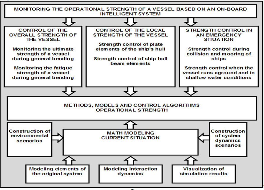
Fig. 1. Conceptual model of an integrated computing complex control of the operational strength of the vessel
Since the risk of destruction of the beam structures of the ship's hull is determined by the value of the maximum relative plastic elongations of the beam material in the area of the dent, the on-board intelligent system has to monitor these elongations. The operation of the local strength control unit of the on-board intelligent system in real time requires the use of calculation methods that ensure minimal expenditure of computing power while maintaining satisfactory accuracy of the result obtained. With such tough restrictions, the use of generally accepted methods, for example FEM, is not always possible, since the calculation time for most practical tasks is an order of magnitude longer than when using engineering methods [5-7, 10].
These make it possible to significantly reduce the number of unknown variables that should be determined in the process of structure deformation analysis in comparison with numerical calculation methods, and provide the ability to analyze the structures deformation beyond the elastic limit in real time mode. The implementation of such a unit in the on-board intelligent operational strength monitoring system will allow the navigator to make timely decisions to change the vessel's operating mode, for example, to stop fishing in glagons. This will not only reduce the amount of damage to ship hull structures, but would also prevent the loss of ships, as was the case, for example, with the large fishing freezer trawler “Kapitan Bolsunovsky” that carried out fishing in conditions of glagons impact on the hull [11]. The analysis showed that the use of engineering methods in the tasks of studying the deformation of beam structures of ship hulls instead of numerical methods enables to reduce the calculation time by one to two orders of magnitude, depending on the specific problem, while maintaining the required accuracy.
The setting of the problem
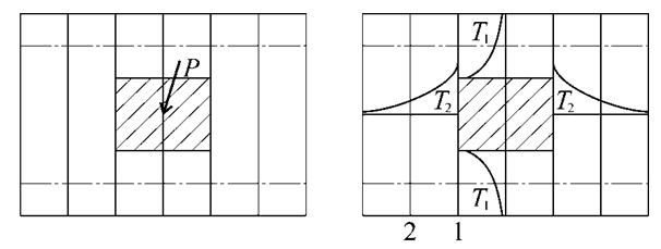
The accuracy of engineering calculations is directly related to taking into account the physical and geometric features of the deformation of hull structures. The more fully the main dominant factors are taken into account, the more accurate the result will be. Let us consider the problem of deforming a locally loaded ship grillage (Fig. 2, a). We will build the solution based on the hypothesis “about the instantaneous opening of plastic hinges” [10]. A similar problem has already been considered in [5-7] under the assumption that the frames adjacent to the loaded one do not undergo deformation.
a b
Fig. 2. Side grillage in the process of loading: a – loading scheme; b – longitudinal forces in the grillage elements
Let us complicate this task by assuming that an increase in load leads to deformation of the frames adjacent to the loaded one. In this case, after the formation of the collapse zone, longitudinal forces will arise [7], which will act on adjacent frames (Fig. 2, b). The magnitude of longitudinal forces directed both along the loaded frame (T1) and in the transverse direction (T2) can be assessed by dividing the structure into rigid and flexible connections according to the method described in [10]. Taking into account the sharp attenuation of longitudinal forces, it can be assumed that taking into account the deformation of the first pair of adjacent frames (No. 1 in Fig. 2, b) can be limited to determining the collapse pattern of the grillage. In principle, using a similar scheme, it is possible to consider the influence of deformation of frames more distant from the loading site (No. 2 in Fig. 2, b).
The purpose of this study, in accordance with the above, is to develop a methodology that allows us to take into account the effect of subsidence of frames adjacent to the loaded frame on the deformation of a locally loaded side grillage, and to evaluate the possibility of its use in the local strength monitoring unit of the on-board intelligent system.
Under the action of an intense locally distributed load on the frame of the ship side grillage, it will deform along with the vessel shell plating that acts as an elastic-plastic base and at the same time is an attached girdle. In this case, the design diagram of the loaded frame will have the form of a beam lying on an elastic-plastic base with sequential inclusion of rigidities [5, 7]. In this case, the frames adjacent to the loaded frame will also be deformed due to the action of longitudinal thrust forces (Fig. 3).
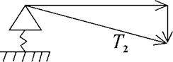
Fig. 3. Scheme of transferring forces to an adjacent frame
This will lead to a decrease in the rigidity of the base of the loaded frame and an increase in its deflections. It should be noted that the greatest decrease in the rigidity of the base of the loaded frame will be observed at the point of loading, since here the deflections of the adjacent frame will be maximum. As you move away from the loading site, the decrease in the rigidity of the loaded frame will be less pronounced, since as you move away from the center of loading, the deflections of adjacent frames will also decrease.
Thus, the elastic-plastic base on which the loaded frame lies will be a base with sequential inclusion of rigidities, and its parameters will continuously change along the length of the loaded frame. However, to a first approximation, the loaded frame can be divided into a number of sections, within which it will lie on a foundation with sequential inclusion of rigidities, the parameters of which remain unchanged within the section, i.e. use the calculation schemes outlined in [5-7].
Development of calculation methods
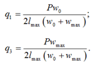
Let us consider the deformation of the frame adjacent to the loaded frame. As a first approximation, we can assume that the load acting on the adjacent frame is applied according to the trapezoidal law (Fig. 4). The intensity of the load on the frame adjacent to the loaded frame is determined from the condition
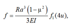
![]()
where w0 is the deflection of the loaded frame at the point where the load is applied; wmax – deflection of the loaded frame at the location of the maximum bending moment.
Considering that in the area of maximum bending moment the shear force is zero, the load intensity of the intermediate frame can be found from the condition:
![]()
where lmax is the distance from the loading point to the maximum bending moment.
After the transformations you can find:
The design diagram of the frame adjacent to the loaded one can be considered as a beam lying on an elastic-plastic base with variable rigidity. The characteristics of this elastic-plastic base are determined by considering the deformation of a cantilever beam-strip in a state of complex bending.
In the elastic stage of operation of a cantilever beam-strip, its deflection can be determined from the expression
where ![]() is the complex bending function;
is the complex bending function; 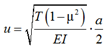 – argument of the complex bending function; a – transverse spacing.
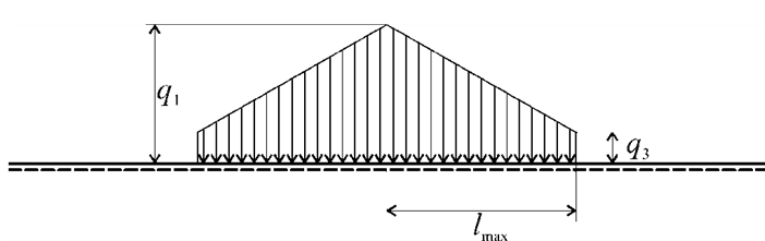
Fig. 4. Calculation scheme of the frame adjacent to the loaded
The rigidity coefficient of the elastic base in this case is determined by the formula
![]()
where b is the width of the beam-strip.
For a plastic string, deflections can be determined from the expression
![]()
Accordingly, the base stiffness coefficient can be found from the expression
![]()
It should be noted that the magnitude of the longitudinal forces acting in the cantilever beams-strips separated from the outer shell and supporting the frame adjacent to the loaded one changes when moving along the frame. It is of greatest importance at the point of loading, gradually decreasing with distance from it. In addition, this force depends on the magnitude of the external load applied to the frame. Thus, the frame adjacent to the loaded one at each loading stage should be considered as a beam lying on a base with a rigidity variable along the length of the beam, i.e.
K = f(z).
To calculate such a beam, along with the methods presented in [12], an approach can be used that involves dividing the beam into separate sections, within which the rigidity of the base is assumed to be constant. At the same time, with an increase in the number of sections, the accuracy of the calculation also increases, however, as the analysis shows, in most problems with accuracy sufficient for practical use, one can limit oneself to dividing the beam into three sections.
In accordance with the above, to determine the deflection of the frame adjacent to the loaded one, we divide it into three sections, two of which are beams of finite length, lying on an elastic-plastic base, and the third is semi-infinite (Fig. 5). Fictitious supports are shown at the boundaries of the plots.
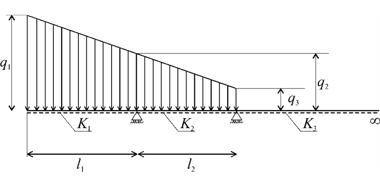
Fig. 5. Calculation scheme for determining the drawdown adjacent to the loaded frame
The equation of the elastic line of each of the sections, within which the rigidity of the base is assumed to be constant, is determined by the known dependencies presented, for example, in [12]. The integration constants included in these expressions are determined from the boundary conditions, taking into account the continuity of the functions of the main bending parameters at the locations of the fictitious supports.
It is advisable to carry out the calculation of the frame adjacent to the loaded frame using the hypothesis of “instantaneous opening of plastic hinges”. As the load on the adjacent frame increases, a plastic hinge will form in the center of the load (Fig. 6), while further calculations are carried out according to the scheme outlined above, taking into account the changed boundary conditions.
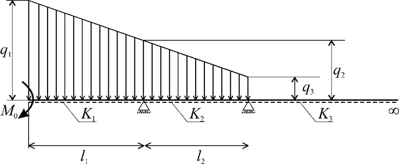
Fig. 6. Calculation scheme of the adjacent frame after the formation of a plastic hinge
The scheme for correcting the rigidity of the elastic-plastic base of the frame is shown in Fig. 7. The following notations are used in the figure: 1 – force-deflection relationship of a beam-strip of a shell plate lying on rigid supports; 2 – approximation of the force-deflection relationship of a beam-sheathing strip without subsidence of supports; 3 – approximation taking into account the settlement of frames adjacent to the loaded one; wadj – deflection of the frame adjacent to the loaded one, determined according to the dependencies presented above; wl – deflection of the loaded frame; w1 – deflection, at which there is a change in the rigidity of the elastic-plastic base of the loaded frame without taking into account the subsidence of frames adjacent to the loaded one; w1k – deflection, at which there is a change in the rigidity of the elastic-plastic base of the loaded frame, taking into account the subsidence of the frames adjacent to the loaded frame. The use of this calculation method makes it possible to determine the deflections of locally loaded frames, taking into account the deformation of beams adjacent to the loaded one.
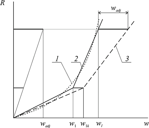
Fig. 7. Scheme for correcting the rigidity of the elastic-plastic base of the loaded frame
Results and discussion
The results obtained were compared with the results of FEM calculations using the ANSYS software package (Fig. 8).
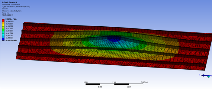
Fig. 8. General view of the deformed side grillage
Figure 9 shows the distribution of plastic elongations at the loading site. The figure shows a strong localization of these elongations that confirms the advisability of using the concept of a plastic hinge [13] when solving such problems.

Fig. 9. Plastic elongations at the point of loading of the side grillage
Figure 10 presents a comparison of the calculation results using the methodology developed by the authors and using FEM using the ANSYS software package. As can be seen from Fig. 10, there is good agreement between the results.
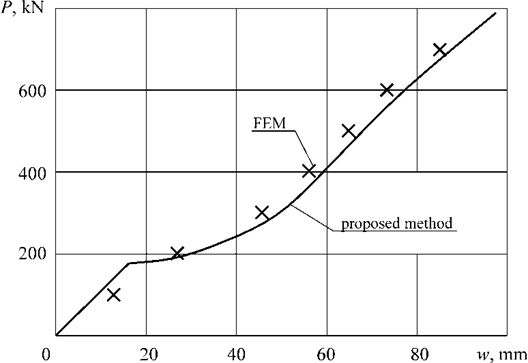
Fig. 10. Comparison of calculation results according to the proposed method and using the FEM
Conclusions
The analysis showed that one of the promising ways to increase the efficiency of fleet operation and navigation safety is the use of on-board intelligent strength monitoring systems. Their development requires calculation methods that allow strength assessment with minimal consumption of computing power. The calculation results using the developed method are in good correspondence with those obtained using FEM that allows us to recommend the presented method for practical use, for example, when implementing a local strength monitoring unit in on-board intelligent systems in real time.
1. Нечаев Ю. И., Петров О. Н. Непотопляемость судов: подход на основе современной теории катастроф. СПб.: Арт-Экспресс, 2014. 368 с.
2. Бураковский П. Е., Нечаев Ю. И. Практическая реализация графоаналитической системы контроля эксплуата-ционной прочности промысловых судов при коррозии корпуса, швартовых операциях и восприятии многократных нагрузок на основе современной теории катастроф // Мор. интеллектуал. технологии. 2014. № 4 (26). Т. 2. С. 24-31.
3. Бураковский П. Е., Нечаев Ю. И. Практическая реализация графоаналитической системы контроля общей прочности промысловых судов на основе современной теории катастроф // Мор. интеллектуал. технологии. 2014. № 2 (24). С. 9-13.
4. Бураковский Е. П., Бураковский П. Е., Нечаев Ю. И., Прохнич В. П. Управление и принятие решений при контроле эксплуатационной прочности судна на основе современной теории катастроф // Мор. интеллектуал. технологии. 2013. № 1 (19). С. 7-14.
5. Бураковский П. Е. Обеспечение прочности корпусных конструкций судов в процессе эксплуатации: моногр. Калининград: Изд-во БГАРФ, 2015. 298 с.
6. Бураковский Е. П., Бураковский П. Е., Нечаев Ю. И., Прохнич В. П. Эксплуатационная прочность судов. СПб.: Лань, 2017. 404 с.
7. Бураковский Е. П., Бураковский П. Е. Нелинейные задачи упруго-пластического деформирования судовых корпусных конструкций: моногр. Калининград: Изд-во Филиала ВУНЦ ВМФ «Военно-морская академия» в г. Кали-нинграде, 2019. 440 с.
8. Пат. 2741671 Рос. Федерация, МПК B63B 79/30, B63B 79/00, B63B 43/00. Способ контроля состояния наружной обшивки корпуса судна / Бураковский Е. П., Бураковский П. Е., Мысник А. В. № 2019137061; заявл. 18.11.2019; опубл. 28.01.2021, Бюл. № 4.
9. Пат. 2689048 Рос. Федерация, МПК B63B 43/00, B63B 9/00. Способ выявления повреждений в наружной об-шивке корпуса судна / Бураковский Е. П., Бураковский П. Е., Мысник А. В. № 2018109313; заявл. 15.03.2018; опубл. 23.05.2019, Бюл. № 15.
10. Бураковский Е. П. Совершенствование нормирования параметров эксплуатационных дефектов корпусов судов. Калининград: Изд-во КГТУ, 2005. 339 с.
11. Завершено расследование дела о крушении траулера «Капитан Болсуновский» в Охотском море весной этого года. URL: https://tass.ru/obschestvo/643489 (дата обращения: 12.07.2023).
12. Папкович П. Ф. Труды по строительной механике корабля: в 4-х т. Т. 1. Изгиб балок и прямолинейных рам. Л.: Судпромгиз, 1962. 576 с.
13. Kazinczy G. Kísérletek befalazott tartókkal // Betonszemle. 1914. N. 2 (6). P. 101-104.
