


Россия
Россия
Россия
Единичные и суммарные мощности электроприводов вентиляторных установок имеют значительные величины, что требует контроля потребления ими электрической энергии в номинальных и пусковых режимах работы для недопущения перегрузки судовой сети, возникновения обменных колебаний мощности между генераторами, снижения качества электроэнергии. Качественная работа электроприводов вентиляторных установок на современных судах осуществляется с использованием преобразователей частоты, позволяющих производить плавные пуски, остановы и регулирование частоты вращения. В проведенных экспериментальных исследованиях для питания асинхронного приводного электродвигателя вентилятора используется преобразователь частоты Optimus Drive AD80-4TD75, в состав которого входит неуправляемый выпрямитель и автономный инвертор. Осциллограммы напряжения, тока и оборотов электродвигателя, полученные в режимах пуска и торможения с применением линейного и S-образного законов управления, показывают хорошие результаты. Использование S-образного закона управления имеет некоторые преимущества перед применением линейного закона, т. к. переходные процессы обладают большей плавностью и электропривод работает более мягко. Специальные возможности преобразователя частоты Optimus Drive AD80-4TD75 позволяют поддерживать постоянство давления и расхода в воздухопроводе при использовании обратных связей в электроприводе. Доказано, что применение пропорционального закона управления частотой питающего напряжения не обеспечивает поддержание давления и частоты при изменении положения воздушных заслонок, в то время как введение постоянной времени интегрирования при использовании пропорционально-интегрального закона управления обеспечивает стабильное поддержание заданных значений давления и расхода во всем диапазоне изменения положения воздушных заслонок.
электротехнический комплекс, устойчивость, генераторный агрегат, преобразователь частоты, электропривод, вентилятор
Introduction
One of the main types of electric drives of ship electrical systems [1, 2] are fan units. Their widespread use on seagoing vessels is explained by the need to ensure a reliable and efficient supply of fresh air to all ship spaces, as well as the removal of used air mixture and exhaust gases from there. Most of the ship spaces, such as the engine room, central control position, holds, tiller room, galley, forepeaks, afterpeaks, incinerators, cabins and many others do not have natural ventilation. Therefore, without a high-quality forced ventilation system, the crew will not be able to be in such spaces and perform their duties. The inflow of fresh air and the removal of contaminated air mixture are also necessary for the operation of ship diesel internal combustion engines located in the engine room. The operation of storage batteries is associated with the release of hazardous gas and is impossible without forced ventilation. Electric drives ensure the operation of fans in refrigerated holds and provision chambers to maintain the required temperature during the transportation of goods and products. The air conditioning system on sea vessels also operates using the ship's forced ventilation system. On sea vessels transporting gas, electric drives of fan units are used as cargo drives for pumping gas, have high power and have a significant impact on the operation of the entire electrical power system of the vessel.
The individual and total capacities of electric drives of fan units are significant, which requires monitoring their electric energy consumption in nominal and starting modes of operation to prevent overloading of the ship's network, occurrence of power exchange oscillations between generators [3, 4], and reduction in the quality of electric power. High-quality operation of electric drives of fan units on modern ships is carried out using frequency converters, which allow for smooth starts, stops, and regulation of rotation speed [5, 6]. Control systems based on frequency converters allow for the operation of ship ventilation systems with maintenance of constant air mixture pressure, and it is also possible to organize operation with maintenance of constant air flow. A ship ventilation system, as a rule, has a complex configuration with many disturbing effects of a non-periodic nature, which requires a systematic approach to the application of control laws and their settings [7-9]. To clarify such issues and develop appropriate recommendations, it is necessary to conduct experimental studies in laboratory conditions and systematize the results obtained.
Methods and materials of the investigation
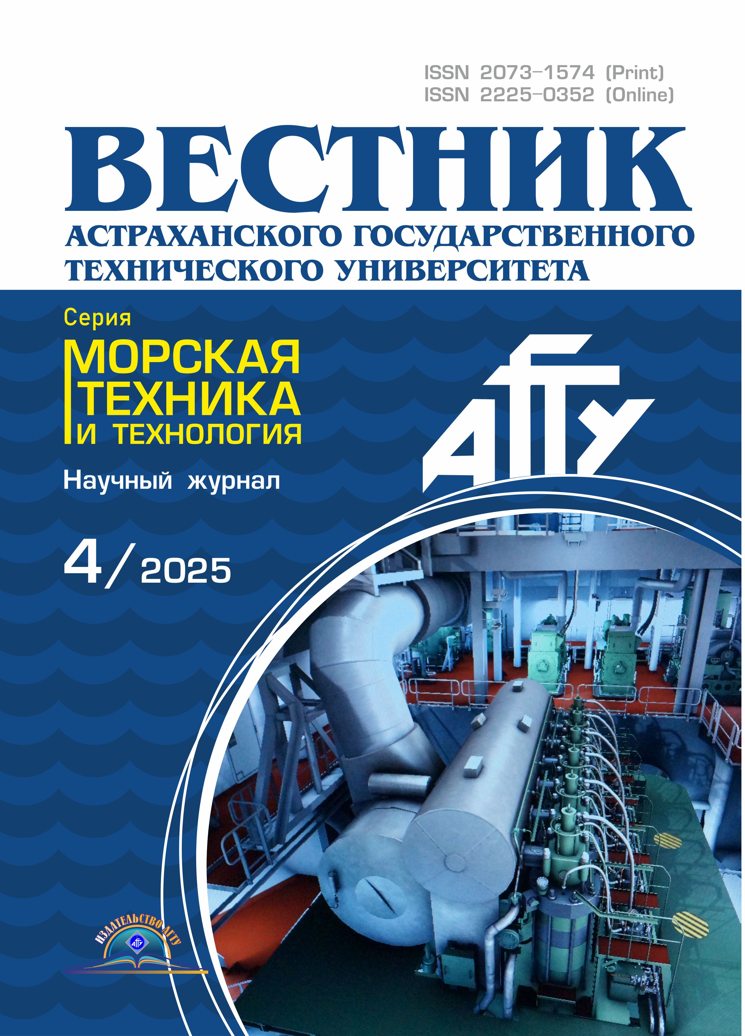
To conduct research on the control system setup and to measure the operating parameters of the electric drive during operation, we use an industrial fan unit, the electric drive of which is an asynchronous electric motor with a squirrel-cage rotor of the AIR63A2 type with a power of 0.37 kW (Fig. 1). A centrifugal (radial) low-pressure fan VR 80-75 is installed in the lower part on a metal base. It has a relative wheel diameter
of 0.9, a nominal rotation speed of 3 000 rpm, a capacity of 0.75-1.77 m3/h, and creates a total pressure of 230-540 Pa at 20 °C. The E40S6-500-6-L-5 pulse speed sensor is mounted directly on the shaft of the fan drive motor. It is an incremental encoder with a supply voltage of 5 V and a maximum consumption current of 60 mA with a resolution of 500 pulses per revolution. The fan creates air pressure in the air duct system with two outputs, each of which has an adjustable ventilation system damper. The ventilation dampers are controlled by AR 24-2 electric drives with a power of 0.7 VA. A DPT-Flow-D-1000 sensor for measuring air pressure and air flow by differential pressure with a supply voltage of 15-24 V, a pressure change range of 0-1 000 Pa, and a flow change range of 100-200 000 m3/h is mounted directly on the air duct. The sensor has a voltage output of 0-10 V and a current output of 4-20 mA. In the sensor setup menu, we set the Flaktwoods calculation algorithm in the Manufacturer sensor parameter, and set the corresponding calibration coefficient
K-VALUE equal to 23 – a parameter that is determined from the fan throughput. We also set the maximum pressure value of 900 Pa and flow rate of 0.6 m3/s in the system under study in the sensor settings.
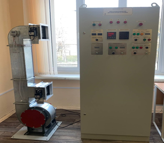
Fig. 1. General view of the ventilation unit
The fan unit control cabinet contains control and indication elements that switch the control circuits on and off, display operating modes and measured values. To measure phase and line voltage, phase currents, active, reactive and full powers, power factors, total active, reactive power and average current, average voltage, power factor and frequency, the SМ96 power meter is connected to the input of the electric motor power supply circuit. The control cabinet also has a measuring controller designed to process pressure and air flow signals from the sensor and generate an output signal using an internal PID controller. Using the built-in PID controller and based on pressure and flow signal readings from the sensor, the measuring controller can automatically control both the frequency converter and damper No. 1. The measuring controller can be configured using specialized software using a laptop.
The Optimus Drive AD80-4TD75 frequency converter with a rated power of 0.75 kW, which includes an uncontrolled rectifier and an autonomous inverter, is used to power the asynchronous drive electric motor of the fan. The frequency converter converts alternating three-phase voltage of 380 V into three-phase voltage with adjustable voltage and frequency values, which ensures regulation of the rotation speed and torque of the asynchronous motor under various control laws. The range of change of the output frequency of the frequency converter is not less than 0-400 Hz and allows smooth regulation of the frequency and voltage on the stator of the asynchronous motor.
A hardware and software measuring system based on a laptop, an input-output board, and DeltaProfi software provides oscilloscope transients from the elements and devices of the stand and the removal of static and dynamic characteristics. Periodic signals can be oscillographed simultaneously for at least 16 signals with a sampling frequency of at least 200 kHz, and instantaneous and averaged signals can be recorded using virtual instruments with a sampling frequency of at least 200 kHz and a duration of at least 5 minutes. The software allows you to use virtual direct current and alternating current ammeters, direct current and alternating current voltmeters, wattmeters, warmeters, frequency meters, phase meters with simultaneous display of at least 16 virtual devices.
Research results
A study of the use of a smooth frequency increase on the stator of the fan drive motor confirmed the possibility of reducing the inrush currents and dynamic loads of the fan electric drive in transient modes. Reducing the starting currents of electric fan drives on the scale of the marine electrical complex is of great practical importance to ensure the stability of its operation. Due to the fact that the use of frequency converters with a direct current link in alternating current electric drives makes it possible to apply various control methods, studies have been conducted during start-up according to the linear law (Fig. 2) and according to the law of the S-shaped ramp (Fig. 3), as well as during braking according to the linear law (Fig. 4) and according to the law of S-shaped ramp (Fig. 5). The experiments, the results of which are shown in Fig. 1-4, were carried out with the upper flap No. 1 closed and the lower flap No. 2.
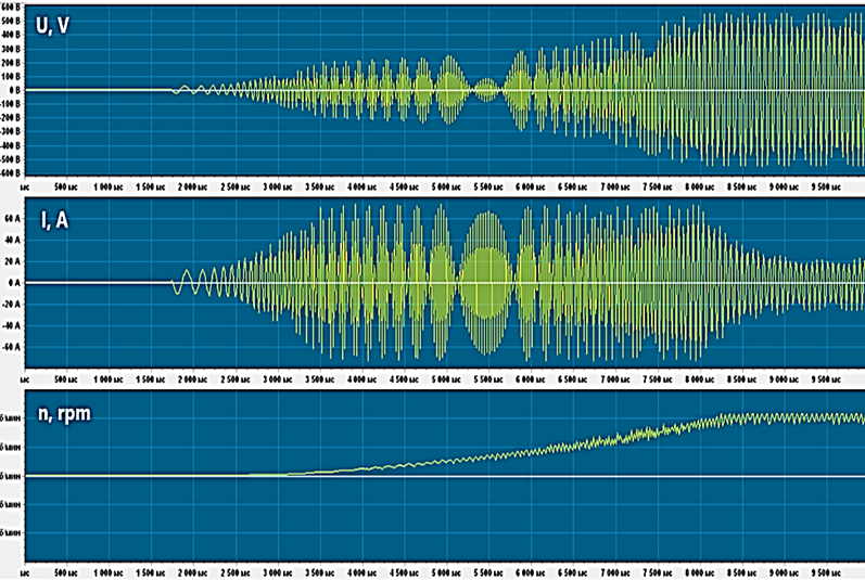
Fig. 2. Oscillograms of voltage U, current I, rotation speed n during frequency starting of the fan electric drive
according to the linear control law
When using the linear law, the fan electric drive accelerated with increasing voltage frequency for a time set in the frequency converter. When starting the fan unit electric drive according to the S-shaped ramp law, the acceleration is delayed at the beginning, and at the end the process accelerates to the set speed. Fan electric drives usually stop due to coasting without the use of special means, but the frequency converter allows for linear braking using the S-shaped ramp law. When braking according to the S-shaped ramp law, the deceleration is faster at first, and at the end the process is delayed.
Fig. 3. Oscillograms of voltage U, current I, rotation speed n during frequency starting of the fan electric drive
according to the S-shaped control law
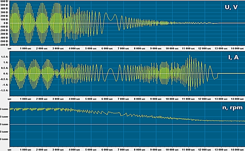
Fig. 4. Oscillograms of voltage U, current I, rotation speed n during frequency braking of the fan electric drive
according to the linear control law
The results obtained in the study of starting and braking of the fan unit using the Optimus Drive AD80-4TD75 frequency converter according to the linear and S-shaped laws showed the possibility of effective use of both control methods, since transient processes are smooth and there are no significant current surges. It should be noted that when using the S-shaped law, there is a possibility of more flexible adjustment of the frequency converter menu parameters, which allows obtaining some advantages for transient processes.
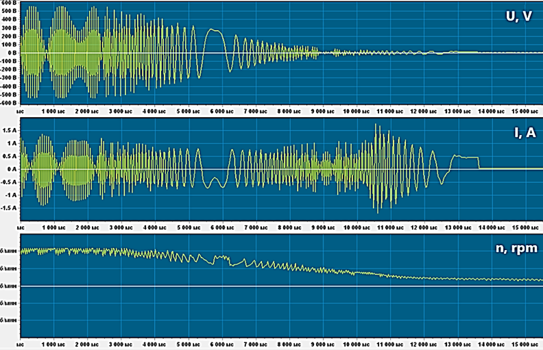
Fig. 5. Oscillograms of voltage U, current I, rotation speed n during frequency braking of the fan electric drive
according to the S-shaped control law
The next stage of experimental studies of the electric drive of the fan unit is devoted to the study of the possibility of maintaining a constant pressure and flow rate by introducing the corresponding feedbacks when using proportional (P) and proportional-integral (PI) control laws in the frequency converter controller.
To conduct studies using pressure feedback, the acceleration and deceleration time was reduced to a minimum value of 0.01 s, the proportionality coefficient was set equal to 0.6 for the P-control law (Table 1), and for the PI-control law, the integration time of the controller was taken to be 3 s (Table 2). In this case, the lower damper No. 2 was closed all the time, and the position of the upper damper No. 1 changed from completely closed to completely open by changing the angle a1. During the experiment, in each position of the damper, n – the rotation frequency of the electric motor, rpm; Un and In – the voltage, V, and stator current, A, of the electric motor; f – the frequency of the voltage supplied to the motor, Hz; P – air pressure, Pa; L – air flow, m3/s; Pn – consumed power, W; Ms – the torque on the shaft of the electric motor as a percentage of the nominal, %.
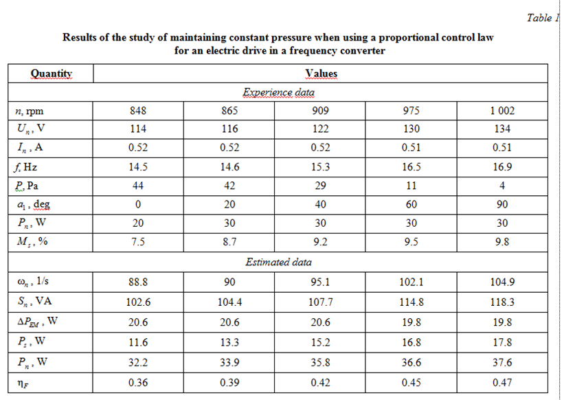
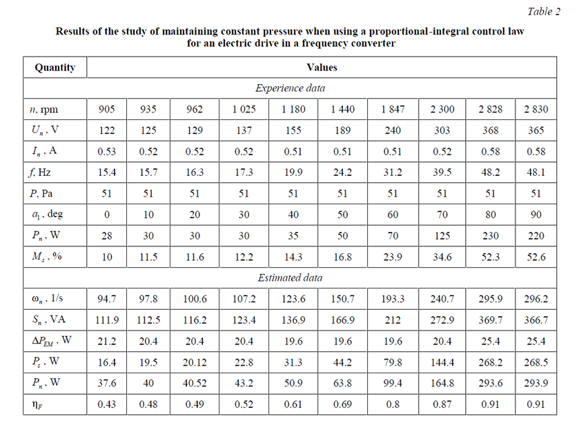
The results obtained during the experimental studies show that proportional control cannot maintain the set pressure value, but the use of the proportional-integral law ensures that the pressure is maintained at the set level of 50 Pa over the entire range of the damper position change from 0 to 90 degrees, i.e. from fully closed to fully open. Changing the position of the lower damper No. 2 from 0 to 90 degrees with the upper damper No. 1 fully closed gave similar results.
Experimental studies were also conducted to maintain the constancy of the flow rate with the upper damper No. 1 fully closed and the lower damper positions from fully closed to fully open with a change in the angle a1. When using flow feedback, the acceleration and deceleration times were reduced to a minimum value of 0.01 s, the proportionality coefficient was set to 0.5 for the P-control law (Table 3), and for the PI-control law, the controller integration time was set to 5 s (Table 4). In this case, the lower damper No. 1 was closed all the time, and the position of the upper damper No. 2 was changed from fully closed to fully open by changing the angle a1.
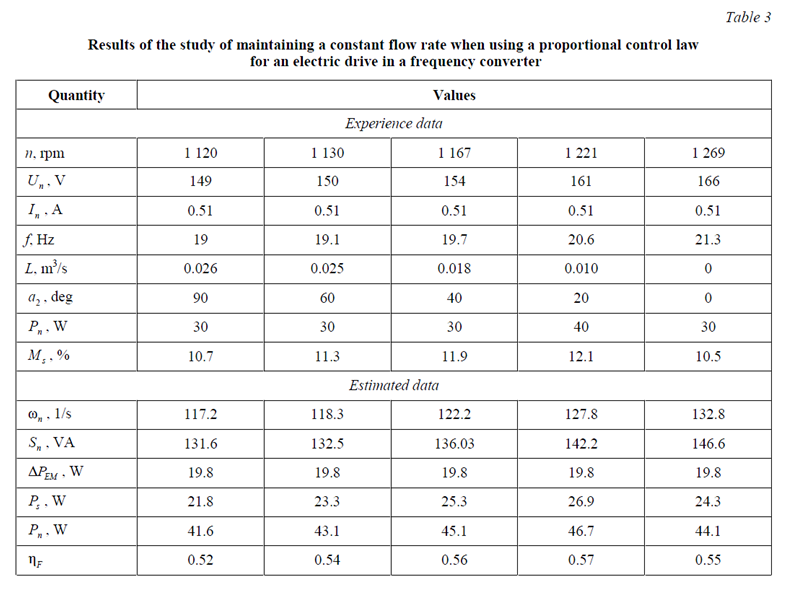
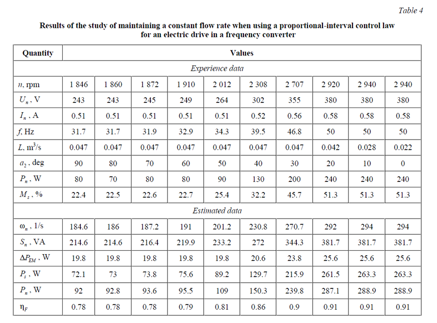
Full power at the frequency converter output, VA:
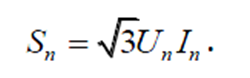 .
.
Electric motor rotation frequency, 1/s:
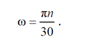 .
.
Electric motor electrical losses, W:
where rs = 25.4 – is the active resistance of the stator phase, Ohm.
The power on the shaft of an asynchronous motor is determined from the parameters of the frequency converter:
 ,
,
where Pmn is the nominal power of the electric motor, W.
Active output power of the frequency converter, W:
 .
.
Fan efficiency:
 .
.
The results obtained during the experimental studies show that proportional control cannot maintain the specified flow rate. but the use of the proportional-integral law ensures that the flow rate is maintained at the specified level of 0.048 m3/s over the entire range of the damper position change from 0 to 90 degrees. i.e. from fully closed to fully open. Changing the position of the upper damper No. 1 from 0 to 90 degrees with the lower damper No. 2 fully closed gave similar results.
Conclusion
The use of frequency converters with a direct current link ensures smooth, soft operation of fan electric drives in marine electrical power system. Experimental studies confirm the absence of significant current and voltage surges in transient processes during starts and braking of fan electric drives. The use of an S-shaped control law has an advantage due to the possibility of dividing the start and braking time into stages with different acceleration and deceleration rates. The task of maintaining constant pressure and flow in the air duct with any change in the positions of the air dampers can be effectively and efficiently solved by using feedback and setting the proportional-integral control law of the electric drive in the frequency converter. Thus, the studies have shown the feasibility and significant advantages of using a frequency converter to control fan electric drives for the entire marine electrical power system.
1. Dar'enkov A., Samoyavchev I., Khvatov O., Sugakov V. Improving energy performance power station of ship with integrated electric propulsion // MATEC Web of Conferences. 2017. V. 108. P. 14002.
2. Sen'kov A. P., Dmitriev B. F., Kalmykov A. N., To-karev L. N. Ship unified electric-power systems // Russian Electrical Engineering. 2017. N. 88 (5). P. 253–258.
3. Савенко А. Е., Голубев А. Н. Обменные колебания мощности в судовых электротехнических комплексах. Иваново: Изд-во ИГЭУ им. В. И. Ленина, 2016. 172 с.
4. Savenko A. E., Savenko P. S. Analysis of Power Os-cillations Parameters in Autonomous Electrical Complexes Using the Method of Customization Charts Designing // Proceedings – 2020 International Ural Conference on Elec-trical Power Engineering, Uralcon 2020 (Chelyabinsk, Sep-tember 22-24, 2020). Institute of Electrical and Electronics Engineers Inc., 2020. P. 400–405.
5. Губанов Ю. А., Калинин И. М., Корнев А. С., Кузнецов В. И., Сеньков А. П. Направления совершенствования судовых единых электроэнергетических систем // Мор. интеллектуал. тех-нологии. 2019. № 1-1 (43). С. 103–109.
6. Авдеев Б. А. Интеллектуальные энергоэффектив-ные системы морских судов // Вестн. Керч. гос. мор. технолог. ун-та. 2021. № 4. С. 99–113.
7. Абакумов А. М., Антропов В. Е., Ведерников А. С., Абакумов О. А. Энергетическая эффективность установок охлаждения природного газа с частотно-регулируемым приводом вентиляторов // Вестн. Самар. гос. техн. ун-та. Сер.: Технические науки. 2019. № 3 (63). С. 94–104.
8. Абакумов А. М., Кузнецов П. К. Комбинированное управление электроприводами вентиляторов установок охлаждения газа // Вестн. Самар. гос. техн. ун-та. Сер.: Технические науки. 2021. Т. 29. № 3 (71). С. 67–82.
9. Abdulhy Al-Ali M. A., Kornilov V. Yu., Gorodnov A. G. Optimized the performance of electrical equipment in gas separation stations (Degassing station ds) and electrical submersible pumps of oil equipment for oil Rumaila field // Power engineering: research, equipment, technology. 2019. V. 21. N. (1-2). P. 141–145.
