


Россия
Астрахань, Россия
Россия
Россия
Представлены результаты проектирования и постройки экспериментальной установки для изучения поперечных, крутильных, осевых и связанных колебаний судового валопровода. Проведен анализ публикаций, посвященных исследованиям динамических явлений, сопровождающих работу пропульсивного комплекса. Отмечено, что для повышения точности методик расчета и экспериментальных данных механические колебания валов необходимо рассматривать как комбинации, т. е. неизолированно. Описана конструкция экспериментальной установки, работа которой приближена к реальным условиям эксплуатации валопровода. Приведены общие принципы экспериментов, которые можно провести при использовании отдельных компонентов устройства. Работа компонентов установки определяет перечень и диапазон факторов экспериментов. Представлены результаты работы по оценке работоспособности построенной установки путем последовательного включения компонентов и оценки их влияния на напряженно-деформированное состояние валопровода. Регистрация параметров колебаний осуществлялась тензометрической измерительной аппаратурой, закрепленной на поверхности вала. Результаты измерений представлены в виде тензограмм поперечных, крутильных и осевых колебаний вала. Анализ экспериментальных данных выявил наличие отдельных зон динамической неустойчивости при включении в работу соответствующих компонентов установки. Для каждой зоны динамической неустойчивости определены границы и оценены нормальные и касательные механические напряжения. Конструкция установки позволяет повысить точность исследований как отдельных видов колебаний валопровода судна, так и их комбинаций за счет повышения точности имитации работы валопровода в реальных условиях эксплуатации. Основное направление научных исследований, которые будут проводиться на данном устройстве, посвящено решению теоретических и экспериментальных задач повышения надежности судовых энергетических установок.
колебания судового валопровода, экспериментальная установка, комбинации колебаний, резонанс колебаний, измерительная аппаратура
Introduction
A ship's propeller shaft is designed to connect the ship's main engine to the propeller and transmit both torque and axial forces. This operation is accompanied by elastic deformations of the shafts, including bending, torsion, and compression. Shaft line vibrations are a variable component of these deformations and are particularly important for the reliability of the ship's propulsion system, as they can pose a risk to its performance. Torsional, lateral, and axial shaft line vibrations cause additional alternating stresses in the main propulsion system components, reducing their load-bearing capacity. Resonance phenomena accompanying the vibrations can lead to fatigue cracks and shaft failures, and, consequently, to emergency situations threatening the lives of the crew and the ship.
The above circumstances emphasize the need for a comprehensive study of the vibrations of marine propeller shafts and the processes associated with them. Current research on this topic utilizes both analytical [1-3] and experimental methods on ships and experimental plants (experimental installations) [4-6]. The conducted analysis of publications allows us to conclude that a significant portion of the research results are devoted to isolated torsional, transverse, and axial vibrations, and only a small portion of the work is devoted to the consideration of vibrations in non-isolation from each other [7, 8]. The requirements of classification societies recognize torsional vibrations as the main threat to the reliability of propeller shafts; however, their study without taking into account the combined influence of transverse and axial vibrations reduces the accuracy of both the analytical model and the resulting experimental data [9].
The article presents the results of solving the problem of designing and constructing an experimental setup for studying the parameters of both individual types of vibrations and their combinations (coupled transverse-torsional, transverse-longitudinal, torsional-longitudinal).
Design of the experimental setup
Conducting multifactorial experiments to study vibrations in the propeller shafts of full-scale ships is a labor-intensive and expensive undertaking, which can be significantly simplified by constructing an experimental setup. The setup was designed based on consolidated domestic experience in constructing setups simulating the operation of marine propeller shafts [10-12] and existing proprietary developments [8, 13]. The general appearance of the installation is shown in Fig.1.
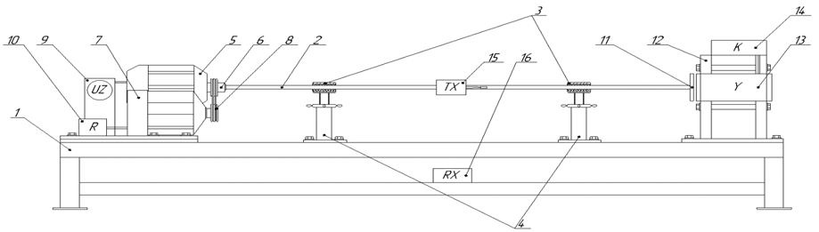
Fig. 1. Experimental setup for studying vibrations of a ship's propeller line:
1 – metal frame; 2 – shaft; 3 – plain bearings; 4 – stands; 5 – asynchronous motor; 6 – sleeve coupling;
7 – load generator; 8 – double-groove V-belt drive; 9 – frequency converter; 10 – power unit; 11 – metal disk;
12 – load unit support; 13 – electromagnet; 14 – electromagnet control unit;
15 – rotor part of the vibration recording device; 16 – stator part of the vibration recording device
The setup consists of a frame supporting an asynchronous motor. The motor shaft is connected to the shaft of a frame-mounted load generator with a power unit via a V-belt drive. The asynchronous motor is flanged to the shaft, which rests on extended bearings with bushings. The extended bearings are secured to height-adjustable stands. A housing containing strain gauge measuring equipment is attached to the shaft surface, linked via radio to a signal receiver for the measuring equipment. A metal disk is attached to the right end of the shaft, and an alternating current (AC) electromagnet with a built-in control device is also mounted on the right side of the frame. The proposed setup design improves the accuracy of ship propeller shaft simulation and expands the range of experimental studies of coupled and individual transverse, torsional, and longitudinal vibrations of propeller shafts.
Features of planning and conducting experiments
The main goal of conducting experimental studies on the proposed setup is to verify the adequacy of mathematical models based on assessing the influence of various factors on the amplitude-frequency response of oscillations. Such studies are considered active experiments, where the phenomenon is studied across the entire range of factors, not smoothly, but only at specific points (minimum, midpoint, maximum). After obtaining data at these points, intermediate values are calculated to obtain an analytical description of the response function.
The operation of the setup's components determines the range and factors of the experiments. An asynchronous motor transmits torque to the shaft via a V-belt drive. To study the torsional vibration parameters of the shaft line at various shaft speeds, it is necessary to generate a pulsed rotating or braking torque with adjustable parameters: amplitude, frequency, and duty cycle, as well as an adjustable braking torque. Torsional vibrations during rotation of the shaft with a disk-shaped flywheel mass are excited using a load generator with a power unit, which is an electric machine operating in generator mode and creating a variable braking load. The braking torque of the load generator is determined by changing the current in the generator's armature winding, which is provided by a power unit with an electronic generator with variable frequency, amplitude, and pulse duty cycle. The main component of the device is a transistor multivibrator with adjustable frequency and pulse duty cycle. The oscillation frequency, pulse duty cycle, and generator output signal level are set by variable resistors. The oscillation frequency is determined by the capacitance of the capacitors. The circuit is powered by an external power supply.
The study of transverse vibration parameters is enabled by the ability to regulate the excitation load frequency by varying the asynchronous motor shaft speed using a frequency converter. The study of transverse vibration resonance is possible by varying the oscillatory system parameters: liner material, bearing clearance, shaft material and diameter, support arrangement, and shaft alignment.
To study longitudinal vibrations during operation of the installation, the possibility of magnetic interaction between a disk made of ferromagnetic material and an AC electromagnet with a control device with a given amplitude, frequency and duty cycle is provided.
Experiments to study transverse-torsional vibrations of a shaft line are possible by simultaneously operating a load generator with a power unit, varying the frequency, amplitude, and duty cycle, and by changing the flywheel mass (disk size) and selecting system parameters that alter the transverse vibration parameters (liner material, plain bearing clearance, shaft material and diameter, support arrangement, and shaft alignment), as well as the shaft rotational speed. When the frequency of external forces matches or is a multiple of the system's natural vibration frequency, the strain gauge instrumentation obtains experimental data on the resulting resonance. Similarly, the setup allows for the study of combinations of transverse-longitudinal and torsional-longitudinal vibrations.
Thus, when conducting research on an experimental setup, the ability to vary a number of factors is provided. When planning an experiment, for each factor, taking into account the fundamental limitations, the range of variation can be estimated, within which the baseline level and variation interval are selected.
Evaluation of the performance of the experimental setup
The setup includes a 3 kW AIR100S4 asynchronous motor with a shaft speed of up to 1 500 rpm, which drives a 1-meter-long shaft made of grade 35 steel with a diameter of 25 mm. A 200 mm-diameter metal disk weighing 2 kg is attached to the right end of the shaft. The motor shaft speed is varied during the experiment using a frequency converter. The load generator with a power unit is a P22M electric motor with a power of 0.95 kW and a shaft speed of up to 1 500 rpm, operating in generator mode and creating a variable braking load with an integrated power unit. Extended supports with a casing and a bushing simulate the operation of a propeller shaft resting on bow and stern tube bearings. The internal diameter of both bushings is 25 mm; the bushings can be replaced with larger internal diameter liners in 0.5 mm increments up to 28 mm. The liner material is caprolon; fluoroplastic, rubber, and babbitt can also be used. The supports, which are height-adjustable, allow the shaft axis position to be adjusted relative to the asynchronous motor axis by up to 5º, depending on the selected liner diameter in extended supports. A housing with strain gauge measuring equipment is fixed to the shaft surface. The equipment includes: 2FKP-5-400 strain gauges connected in a bridge circuit, a strain gauge with a CAN interface, and a CAN-to-radio channel interface converter. A receiver of the measuring equipment signals is mounted on the lower part of the frame: a Radio Channel-to-CAN interface converter, an Ethernet/Wi-Fi-to-CAN interface converter [8]. The setup components are mounted on a fixed frame (Fig. 2).
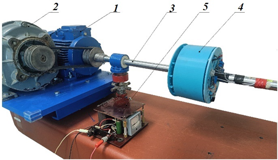
Fig. 2. Components: 1 – electric motor; 2 – load generator; 3 – shaft;
4 – device for recording vibration parameters; 5 – power unit
The system's performance was tested by sequentially connecting the system's components and assessing their impact on the shaft line's stress-strain state. The vibration parameter measurement results are shown in Fig. 3-5.
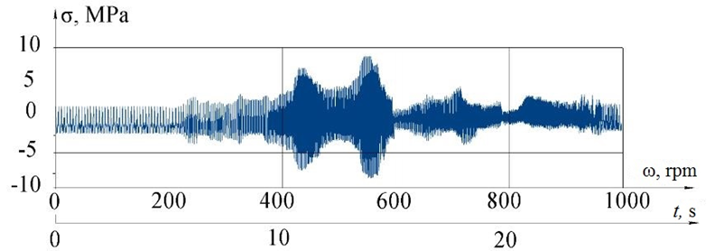
Fig. 3. Experimentally obtained tensogram of vibrations during transverse vibrations of the shaft
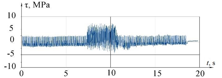
Fig. 4. Experimentally obtained oscillation tensogram during simulation of torsional oscillations
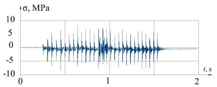
Fig. 5. Experimentally obtained tensogram of oscillations under periodic axial load on the shaft
Transverse vibrations of the shaft were recorded by measuring equipment at engine speeds ranging from 50 to 1 000 rpm. With a diametrical clearance of 3 mm in the aft bearing, the shaft detached from the bearing in the near-resonance and resonant zones. Consequently, the resonance phenomenon was observed not at a single frequency, but across the entire frequency range. Normal stresses in the ranges from 420 to 460 rpm and from 540 to 575 rpm reached 7 and 9 MPa, respectively.
Torsional vibrations of the shaft line were simulated by activating a load generator while the shaft rotated at a constant frequency of 50 rpm. The oscillation strain gauge recorded a region of dynamic instability between the 7-th and 12-th seconds of operation. Torsional vibration stresses did not exceed 5 MPa.
The variable axial load reached 6 MPa at a frequency of 20 Hz. The influence of shaft deflection during rotation was eliminated by using a built-in digital filter.
Conclusion
The developed experimental setup allows for the study of ship propeller shaft model vibrations: longitudinal, transverse, torsional, and their combinations. The novelty of the technical solutions is demonstrated by the following elements:
1. The installation of a load generator with a power unit and its shaft connected to the asynchronous motor shaft via a V-belt drive allows for the modeling of torsional vibrations of ship propeller shafts for study by transmitting a pulsed torque between the shafts with adjustable parameters: amplitude, frequency, and duty cycle.
2. Extended supports with bushings of varying clearances allow the setup's operation to approximate conditions typical of a ship's propeller shaft.
3. Making the supports height-adjustable expands the scope of research into the influence of shaft alignment on transverse vibration parameters.
4. Mounting a housing with strain gauge measuring equipment on the shaft surface allows for the placement of primary transducers, sensors, and a signal transmitter in close proximity to the object of study, which improves the accuracy of the obtained experimental data and reduces transmission time. Mounting a receiver for measuring equipment signals in the lower part of the frame ensures safe experimental studies and the ability to connect a computer for signal transmission via wires.
5. Mounting an AC electromagnet with a built-in control device enables longitudinal vibration studies.
The design of the experimental setup allows for increased accuracy in studying both individual types of propeller shaft vibrations and their combinations by increasing the accuracy of simulating propeller shaft operation under real operating conditions.
Conducting subsequent experimental studies and processing the dataset will allow us to study the combined effects of vibrations on the reliability of marine propeller shafting. The results of these studies can be extended to structurally similar full-scale propeller shafting systems based on the geometric, kinematic, and dynamic similarities of the processes. The obtained experimental data will allow us to establish relationships for predicting the dynamic properties of propeller shafting systems based on fundamentally new phenomena.
1. Сутырин В. И., Шинкаренко И. А. Расчет крутильных колебаний судового валопровода буксира проекта 1606 // Изв. Калининград. гос. техн. ун-та. 2018. № 49. С. 261–272.
2. Румб В. К., Хоанг В. Т. Определение упругих и демпфирующих свойств упорного подшипника при рас-чете осевых колебаний судовых валопроводов // Мор. вестн. 2019. № 1 (69). С. 64–67.
3. Мамонтов В. А., Абачараев И. М., Булгаков В. П., Кушнер Г. А. Автоматизация методики расчета собственной частоты поперечных колебаний гребного вала // Вестн. Астрахан. гос. техн. ун-та. Cер.: Морская техника и технология. 2019. № 1. С. 63–70. DOIhttps://doi.org/10.24143/2073-1574-2019-1-63-70.
4. Горбачев М. М., Букин В. Г., Васильев А. В. Экспериментальное исследование влияния свойств моторных масел на уровень крутильных колебаний валопровода судна типа «Ярославец» // Вестн. Гос. ун-та мор. и реч. флота им. адм. С. О. Макарова. 2024. Т. 16. № 6. С. 964–973. DOIhttps://doi.org/10.21821/2309-5180-2024-16-6-964-973.
5. Лапин Ю. А., Грибиниченко М. В. Экспериментальное исследование развития крутильных колебаний в пропульсивном комплексе с мод при медленном и быстром проходе резонансной зоны // Техническая эксплуатация водного транспорта: проблемы и пути развития: материалы VII Нац. (Всерос.) науч.-техн. конф. (Петро-павловск-Камчатский, 14–15 ноября 2024 г.). Петропав-ловск-Камчатский: Изд-во КГТУ, 2025. С. 164–168.
6. Кушнер Г. А., Мамонтов В. А., Халявкин А. А. Экспериментальное исследование параметрических колебаний валопроводов судов // Вестн. Астрахан. гос. техн. ун-та. Сер.: Морская техника и технология. 2015. № 1. С. 21–26.
7. Румб В. К., Самсонов А. В. Гребной винт – источник упругой связи крутильных и осевых колебаний судового валопровода // Тр. НТО судостроителей им. акад. А. Н. Крылова. 2003. № 1 (1). С. 58–61.
8. Кушнер Г. А. Исследование связанных колебаний гребного вала экспериментального судна // Тр. Крылов. гос. науч. центра. 2023. № 4 (406). С. 109–118.
9. Дьяченко А. В., Горбачев М. М. Актуальность измерения связанных колебаний в судовых энергетических установках // Развитие энергетики водного транспорта, информационных и энергосберегающих технологий: сб. материалов II Всерос. конф. (Казань, 09–10 декабря 2024 г.). Казань: Изд-во ВГУВТ, 2024. С. 176–179.
10. Покусаев М. Н., Глухов А. Н., Золин О. П. Стенд для испытаний демпферов судовых двигателей // Изв. высш. учеб. заведений. Машиностроение. 2005. № 5. С. 54–60.
11. Лапин Ю. А., Герман А. П., Бурлакова Н. Н. Анализ методов расчета крутильных колебаний судовых валопроводов // Вестн. Инженер. шк. Дальневост. федерал. ун-та. 2020. № 3 (44). С. 71–79. DOIhttps://doi.org/10.24866/2227-6858/2020-3-7.
12. Гирин C. Н., Матвеев Ю. И. Оценка качества центровки судовых валопроводов с учетом напряженного состояния материала // Науч.-техн. сб. рос. мор. рег. су-доходства. 2023. № 72-73. С. 60–67.
13. Кушнер Г. А., Мамонтов В. А., Шахов В. В. Опыт проектирования и постройки экспериментальных установок для исследований колебаний судового валопровода // Каспий и глобальные вызовы: материалы Междунар. науч.-практ. конф. (Астрахань, 23–24 мая 2022 г.). Астрахань: Изд-во АГУ, 2022. С. 201–206.
