


Россия
Россия
Актуальность настоящего исследования обусловлена критической зависимостью отечественного судового двигателестроения от импортных технологий демпфирования крутильных колебаний, усугубленной прекращением поставок и сервисного обслуживания зарубежных пружинных и силиконовых демпферов. Со-здание отечественных демпферов представляет особую важность в свете задач технологического суверенитета российского государства. Проведены сравнительные лабораторные тестирования пружинного и силиконового демпферов для количественной оценки эффективности демпфирования крутильных колебаний. Исследуются силиконовый демпфер и прототип пружинного демпфера, разработанного на основе авторской методики со-здания, c применением технологии реверс-инжиниринга серийного образца пружинного демпфера модели D90/37 фирмы Geislinger. Критерием эффективности являлось снижение амплитуды крутильных колебаний, оцениваемое по величине напряжений в валах лабораторного стенда в зависимости от частоты вынужденных колебаний и частоты вращения стенда. Установлено, что в области частот вращения стенда до 250 мин–1 эффективность демпферов сопоставима (снижение напряжений в 2,3–3,5 раза при нерезонансных и до 9,7 раз при резонансных колебаниях). При частоте свыше 250 мин–1 прототип пружинного демпфера является более эффективным, снижая амплитуды напряжений в 1,8 раза против 1,4 раза у силиконового демпфера. Выявлены наиболее опасные дефекты: для прототипа пружинного демпфера – блокировка листовых рессор, приводящая к росту напряжений в 4 раза; для силиконового – заклинка маховой массы, вызывающая рост напряжений в 2,8 раза. Полученные результаты могут быть использованы при создании отечественных аналогов демпферов и разработки методики безразборной диагностики их технического состояния.
судовая дизельная установка, прототип пружинного демпфера, силиконовый демпфер, крутильные колебания, амплитуда напряжений, сравнительные лабораторные тестирования
Introduction
To dampen torsional vibrations in modern marine diesel plants of foreign companies MAN B&W, Caterpillar, Wärtsilä, Sulzer, along with silicone, elastic-friction dampers are also used [1], the main elastic elements of which are leaf springs or sleeve springs (in the terminology of the FAI Rules, “Russian Maritime Register of Shipping” – spring dampers) [2, 3]. The creation of competitive domestic spring (hereinafter referred to as SD) and viscous torsional vibration dampers (hereinafter referred to as VD) is hampered by complex system limitations [4]. The import substitution policy initiated by requests from leading industrial cooperatives to Astrakhan State Technical University (Sinara-Transport Machines JSC, Rosatom State Corporation, United Shipbuilding Corporation JSC) is facing a complete cessation of supplies of imported analogues. The situation is also aggravated by the acute shortage of their own engineering competencies and the absence in the regulations of classification societies of an approved methodology for non-selective diagnostics of SD, which makes maintenance of such devices in operation almost impossible [5].
The purpose of the research is to conduct comparative laboratory tests of the SD-prototype and the VD to quantify the effectiveness of damping torsional vibrations.
Research materials
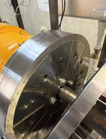
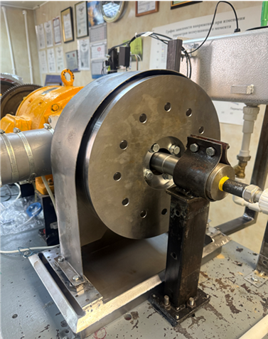
Objects of research: VD and SD-prototype (the general view is shown in Fig. 1), developed on the basis of the author's creation methodology and using reverse engineering technology of the serial SD model D90/37 from Geislinger [6].
During the experiments, a laboratory stand and the following measuring equipment were used (Fig. 2) of the Marine Technology Service Test center (hereinafter referred to as TC MTS), certificate of recognition of the FAI “Russian Maritime Register of Shipping” No. 24.03.02.05546.141 dated 07.11.2024, FAI “Russian Classification Society” No. 10848 dated 04.28.2025:
– a laboratory stand simulating a marine propulsion system, equipped with a special system for supplying the working fluid (lubricating oil) to the SD-prototype, designed for its testing;
– strain gauge complex Astech Electronics (Great Britain);
– laptop with Astech Electronics software – Astech C-Range Logging Version 2.5.0.1825;
– set of strain gauge resistors Zemic BBF400-5AA-A(11)-BX30 – electrical resistance 400.3 ± 0.2 Ohms;
– laser tachometer “CEM” AT-6 – accuracy ±0.05%;
– pyrometer Testo 830-T1 – accuracy ±1.5 °C or ±1.5% of the measurement value (from +0.1 to +400 °C).
 |
 |
|
a |
b |
Fig. 1. General view of the SD-prototype installed as part of the laboratory stand:
a – the components of the SD-prototype; b – the SD-prototype assembly
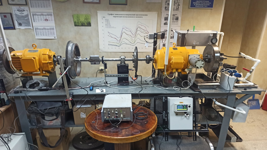
Fig. 2. General view of the laboratory stand and measuring equipment of the TC MTS
The performance criterion was a reduction in the amplitude of torsional vibrations, assessed by the magnitude of stress in the laboratory rig shafts depending on the frequency of forced vibrations and the rig's rotational speed. Control measurements were conducted in two cross-sections: the main cross-section (the shaft between small flywheel № 1, hereinafter referred to as the SF shaft, and large flywheel, hereinafter referred to as the LF shaft), determined as the nodal cross-section based on the results of free torsional vibration calculations, and the secondary cross-section (the shaft between clutch № 1 and small flywheel № 1 – SF). An analysis of the experimentally estimated maximum stresses in the cross-sections of the laboratory rig shafts without the installed damper revealed that the resonant frequency of torsional vibrations is 47.6 Hz.
Investigation of the influence of the technical condition of the VD on the development of torsional vibrations
During the experiments, the following types of VD technical condition were modeled:
– normal technical condition;
– condition with leakage of silicone liquid;
– the condition when the flywheel is jammed inside the damper housing.
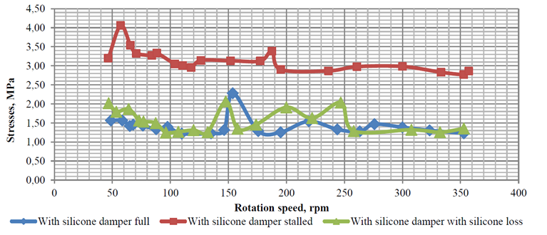
All three cases of the technical condition of the VD were considered on the laboratory stand, and the comparison results under the influence of resonant frequencies of forced vibrations are shown in Fig. 3.
As can be seen from Fig. 3, the jamming of the flywheel mass leads to an increase in stresses by 2.85 times (maximum). The partial loss of silicone in the damper also leads to an increase in stresses in this case by 1.8 times (maximum), but in a wide range of rotational speeds, the increase in stresses is not as unambiguous as when the flywheel is jammed. It is clear that the most dangerous condition will be a complete loss of silicone, which, according to earlier studies by M. N. Pokusaev, M. M. Gorbachev and A. N. Glukhov [7], will lead to a 2-fold increase in stress.

а
b
Fig. 3. Stress development during simulation of the technical condition of a VD under the influence of resonant vibrations: a – in the LF shaft; b – in the SF shaft
Investigation of the influence of the technical condition of the SD-prototype on the development of circular oscillations
For a SD-prototype, it is necessary to consider the following options for modeling its technical condition:
– the normal technical condition of the SD-prototype with the working condition of the leaf springs and ensuring full oil flow through the damper housing;
– a dry SD-prototype without oil supply is a situation that is possible under real operating conditions if the flow parts of the oil supply system and the flow part of the SD are contaminated and run for some time, sufficient for oil to flow out of the SD;
– with oil, but without flowing through the body of the SD-prototype – a situation that precedes the dry state, that is, when the oil is still contained in the flow part, but does not have sufficient supply from the system;
– SD-prototype with wedging leaf springs – a situation that may occur if they overheat with insufficient cooling or are damaged.
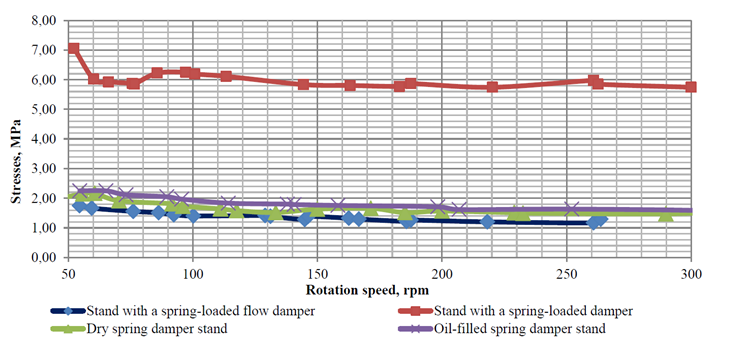
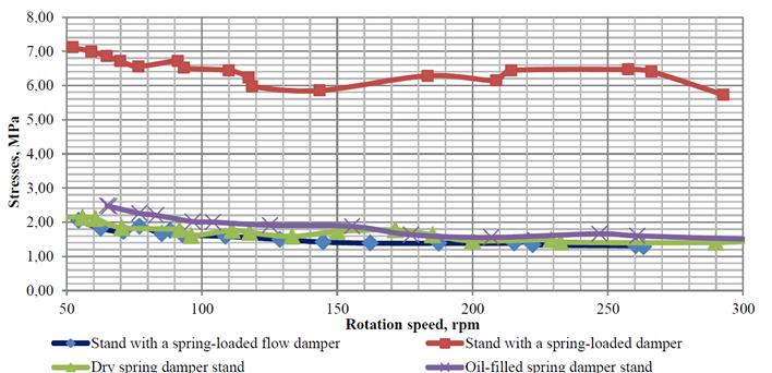
The results of the considered cases for both sections of the stand are shown in Fig. 4.
a
b
Fig. 4. Stress development under the influence of resonant vibrations: a – in the LF shaft under different technical conditions of the SD-prototype; b – in the SF shaft when modeling the technical condition of the SD-prototype
The results obtained, shown in Fig. 4, allow us to draw the following conclusions:
1. The most dangerous technical condition is the blocking of leaf springs, which leads to a voltage increase of up to 4 times with resonant forced fluctuations compared to the normal technical condition.
2. The termination of the oil flow leads to an additional increase in stresses of the order of 1.3-1.4 times compared with the normal technical condition of the SD-prototype.
3. A flow-through oil supply system is more necessary for cooling and lubricating the rubbing parts of the SD-prototype.
4. The lack of oil in the SD-prototype leads to an increase in voltage, however, in reality, a similar situation with a lack of oil in the flow part can occur during prolonged operation of a diesel engine and is most often eliminated using a monitoring system. A similar practice of signaling changes in oil pressure when it is applied to the damper is implemented by Geislinger in Sulzer marine diesel engines, etc.
Evaluation of the effectiveness of the PD prototype and SD when installed as part of a laboratory stand
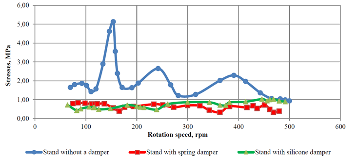
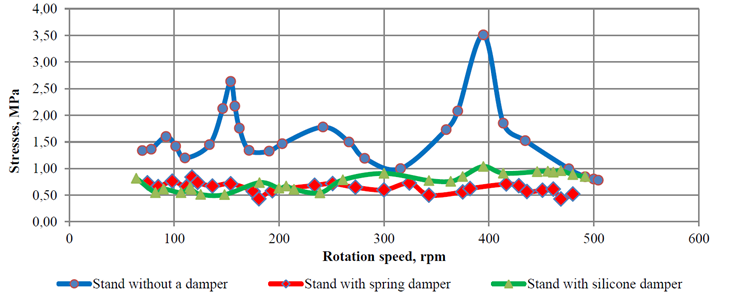
When installing the SD-prototype and supplying running oil to it, and after subsequent disassembly and installation of the VD, stress development graphs were obtained, shown in Fig. 5. These graphs were obtained provided that the frequency of forced vibrations was maintained at 47.6 Hz.
a
b
Fig. 5. Graphs of stress development during installation of the SD-prototype and VD: a – for the LF shaft; b – for the SF shaft
As can be seen from Fig. 5, both dampers effectively reduce the level of both resonant and non-resonant stresses and equalize the voltage dependence on the rotation frequency. At the same time, in the range of rotation speeds up to 250 min–1, the SD is more effective, with a further increase in rotation speed, the PD prototype is more effective. This, in particular, may confirm the effectiveness of the PD installation on modern marine high-speed engines.
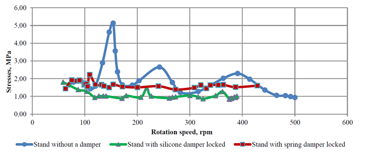
Additionally, a case was considered for such a dangerous state of both dampers as locking the flywheel mass and maintaining the frequency of forced vibrations at 47.6 Hz, due to the fact that this frequency of torsional vibrations is resonant, according to experimental studies. The results of the study are shown in Fig. 6, according to which, when exposed to non-resonant vibrations when the flywheel mass of the dampers is blocked, the voltage is lower than in the installation without dampers, while the SD-prototype voltage is on average 1.6 times higher than when the VD is blocked. It can also be noted that when the SD-prototype is blocked at certain rotation frequencies, the voltages become on average up to 1.6 times higher than without installing a damper in general, which once again underlines the importance of maintaining the good technical condition of leaf springs. It should also be noted the danger of blocking the control panel, which can lead to an increase in voltage (and an excess at a rotation speed of up to 100 min–1) up to the level of values typical for the stand without installing a damper, however, this effect is less pronounced than when blocking the prototype control panel.
a

b
Fig. 6. Graphs of the stress development when the flywheel mass of the SD-prototype and the VD is jammed under the influence of vibrations with a frequency of 47.6 Hz: a – in the LF shaft; b – in the SF shaft
The reliability of processing the results of experimental studies is ensured by using well-known recommendations and guidelines contained in the works of V. P. Terskikh [8], P. A. Istomin [9], V. K. Rumb, A. A. Pugach [10], M. A. Minasyan [11] and the Rules of classification societies – RMRS and RCS [2, 3].
Conclusion
Thus, the following conclusion can be drawn on the effectiveness of the SD-prototype and VD when installed as part of a laboratory stand, which determines the scientific novelty of the study:
1. At a rotation speed of up to 250 min–1, the voltage amplitude decrease for both the SD-prototype and the VD is on average the same 2.3-3.5 times for non-resonant oscillations, and up to 9.7 times for resonant maximum voltages.
2. At a rotation frequency of over 250 min–1, the voltage amplitude decreases by 1.8 times when installing the SD-prototype, and by 1.4 times when installing the VD with non-resonant vibrations, and 3.5 times and 2.7 times, respectively, with resonant vibrations.
3. At a rotation speed of over 470 min–1, it was noted that the voltages without installing a damper and with the installation of the VD are almost identical (within 10%), and with the installation of the SD-prototype, a decrease in amplitudes is achieved by 2.6 times.
4. The SD-prototype will reduce voltages more efficiently than the VD at rotational speeds above 250 min–1, which justifies its use in modern high-speed diesel engines.
5. The greatest danger for the SD-prototype is jamming and damage to the leaf springs, which can be caused by both damage to them and overheating in case of malfunction of the oil supply system.
1. Ефремов Л. В. Теория и практика исследования крутильных колебаний силовых установок с применением компьютерных технологий: моногр. СПб.: Наука, 2007. 276 с.
2. НД № 2-020101-174. Правила классификации и по-стройки морских судов. Ч. VII. Механические установки. СПб.: Изд-во РМРС, 2025. 109 с.
3. Руководство Р.009-2004. Расчет и измерения кру-тильных колебаний валопроводов и агрегатов. М.: Изд-во РКО, 2016. 24 с.
4. Покусаев М. Н., Сибряев К. О., Горбачев М. М., Ибадуллаев А. Д. Разработка модельного пружинного демпфера крутильных колебаний // Вестн. Моск. гос. техн. ун-та им. Н. Э. Баумана. Сер.: Машиностроение. 2023. № 4 (147). С. 124–138. DOIhttps://doi.org/10.18698/0236-3941-2023-4-124-138.
5. Сибряев К. О., Покусаев М. Н., Горбачев М. М., Ибадуллаев А. Д. Работоспособность механических демпферов крутильных колебаний судовых двигателей внутреннего сгорания // Вестн. Астрахан. гос. техн. ун-та. Сер.: Морская техника и технология. 2022. № 1. С. 35–41.
6. Покусаев М. Н., Ибадуллаев А. Д., Сибряев К. О., Горбачев М. М., Хоменко Т. В. Разработка прототипа пружинного демпфера крутильных колебаний с примене-нием технологии реверс-инжиниринга // Вестн. Инженер. шк. Дальневост. федерал. ун-та. 2024. № 4 (61). С. 54–63.
7. Глухов А. Н. Исследование функциональных свойств силиконовых демпферов судовых дизелей для решения задач диагностики: дис. … канд. техн. наук. Астрахань, 2006. 125 с.
8. Терских В. П. Крутильные колебания валопровода силовых установок: исследования и методы расчета. Л.: Судостроение, 1970. 275 с.
9. Истомин П. А. Крутильные колебания в судовых ДВС: учеб. пособие. Л.: Судостроение, 1968. 304 с.
10. Румб В. К., Пугач А. А. Еще раз о расчетах кру-тильных и осевых колебаний судовых пропульсивных установок с ДВС // Мор. вестн. 2013. Вып. 1 (10). С. 31–33.
11. Минасян М. А. Колебания валопроводов судовых дизельных установок: учеб. пособие. СПб.: Изд-во СПбГМТУ, 2006. 108 с.
