


employee
Kaliningrad, Kalinigrad, Russian Federation
Kaliningrad, Kalinigrad, Russian Federation
Baltijsk, Kalinigrad, Russian Federation
The operation of marine vessels, especially large-tonnage ones, is accompanied by the occurrence of serious damage to hull structures within bow in stormy conditions. A new mechanism to explain the catastrophic destruction of the side grillages of large-tonnage ships in the area of the bow is proposed. Simulation of the process of flow around the fore end when it is digged in a wave using SPH technology showed that when the flow speeds around the fore end occur when the vessel moves in developed waves, there is a sharp drop in pressure in certain areas of the bow end. This circumstance can lead to the occurrence of cavitation that is confirmed by modeling the process of flow around the fore end using ANSYS FLUENT software. During stall cavitation, a cavitation cavern of considerable size may arise, the collapse of which is accompanied by the occurrence of hydrodynamic loads that can destroy hull structures. A calculation method is proposed that allows one to estimate the magnitude of hydrodynamic loads acting on the ship’s hull during the collapse of a cavitation cavern. To prevent damage to the bow in storm conditions, a number of constructive measures have been proposed. One of the options for solving the problem is to install a deck fairing in the bow that eliminates the negative influence of structural cavitators in the traditional design when the bow is digged in the wave. It is also possible to install a compressed air supply system to those areas of the bow where vacuum occurs when a liquid flows around when digged in a wave.
fore end of the vessel, destruction of ship's hull structures, hydrodynamic load, structural cavitator, cavitation cavern, cavity collapse, cumulative jet
Introduction
The experience of ship operation, especially large-capacity ones, indicates that their fore end of the hull structures was seriously damaged [1]. The research [2] presents numerous cases of bulk carriers loss as a result of damage to the fore end. Thus, in August 1991, during a storm in the Indian Ocean, the Greek bulk carrier Melete (length – 228 m) with a cargo of iron ore sank down. A message was received from the vessel that it was heading to repair a crack in the part of the cargo hold 1 [2]. As the investigation showed, the damage could not have been inflicted during loading at the port. It is noted that the ship encountered difficult weather conditions to the south of Madagascar [3].
The ore carrier California Maru (length – 218 m) was wrecked in a storm off the coast of Japan on February 9, 1970. A message was transmitted from the vessel about the water intake through a sudden hole in the fore end. For 21 hours the crew had been fighting against the water flow but the vessel sank down [4].
Peculiarities of the damage to the fore ends of large-capacity vessels in stormy conditions
In 1991, the oil ore carrier Atlas Pride (length – 326 m, width – 52 m) suffered serious damage in adverse weather conditions in the region of South Africa [5] (Fig. 1).
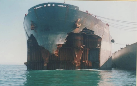
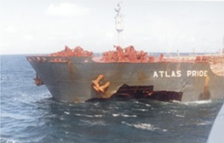
a b
Fig. 1. Damaged bow end of the oil ore carrier Atlas Pride [5]: a – front view; b – side view
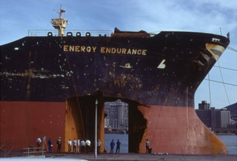
Also, as a result of being caught in a storm and exposed to waves, the Energy Endurance tanker received holes in the fore end [6] (Fig. 2).
Large volumes of destruction of the side and bottom shell plating were observed on the bulk carrier Marcona Trader that ran into gale March 1981, 300 miles to the west of the Midway Islands in the Pacific Ocean [7, 8] while transporting cargo from San Francisco to Japan (Fig. 3).
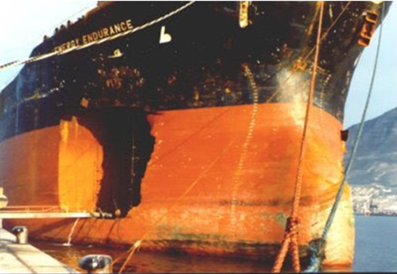
a b
Fig. 2. Damaged bow of the Energy Endurance tanker [6]: a – front view; b – side view
As a result of the impact of waves, a hole measuring 2.4 × 8.5 m was formed in the fore end of the hull of the bulk carrier Marcona Trader.
In the same area of the Pacific Ocean, August 8, 1980, the bulk carrier Chi Star [9] received similar damage in storm conditions, in the fore end of which a serious hole was discovered (Fig. 4). At the time, the ship was to the north of Midway Islands en route from Los Angeles, California, to Sakai, Japan, with a cargo of coal. It is noted that the root cause of such damage is unknown and is unlikely to ever be established [9].
Traditionally, the damage to the fore ends presented above is explained by wave impacts; some sources note that such damage can be caused by exposure to anomalous waves (rogue waves) [10]. According to estimates obtained in recent years, when such waves hit, the pressure on the ship’s hull can reach 980 kPa [10] that is about 100 tons per 1 square meter. Therefore, it seems interesting to assess how often such situations can occur that requires assessing the probability of ships encountering anomalous waves (rogue waves). A similar assessment was carried out by the authors in [11, 12], while within the framework of the developed mathematical models, anomalies form Poisson field and their parameters (velocity, half-width, lifetime) are random variables. If these random variables are independent, the danger function of a ship encountering an anomaly over some time T is determined by the expression
D(T) = 2ITMθMυMρ, (1)
where Mθ – is the mathematical expectation of the anomaly lifetime, s; Mυ – mathematical expectation of the anomaly speed, m/s; Mρ – mathematical expectation of the half-width of the anomaly, m; T – time period during which the probability of a ship meeting an anomalous wave is estimated, s; I – the intensity density of the Poisson flow of anomalies, s–1·m–2.
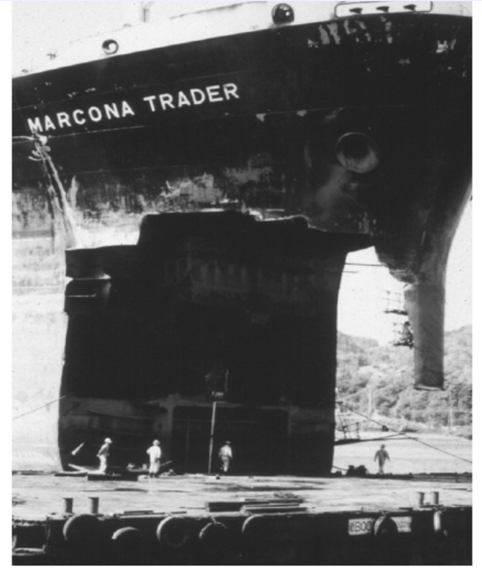
Fig. 3. Repair of damage to the fore end of the hull of the bulk carrier Marcona Trader [7]
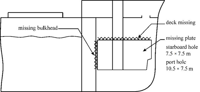
Fig. 4. Damage to the fore end of the bulk carrier Chi Star [9]
The probability of encountering an anomalous wave according to [11, 12] can be found using the dependence
P(T) = 1 – exp[–D(T)].
Due to the insufficient volume of statistical material on the characteristics of anomalous waves, when assessing the probability, the anomaly parameters varied in the range of their actual values. The data on recording anomalous waves from space presented in [10, 13] make it possible to estimate the product of the intensity density of the anomaly flux included in (1) and the mathematical expectation of their lifetime in the value I · Mθ = 5.9 · 10–13 m–2. The assessment shows that the probability of a ship encountering an anomalous wave can be very high [11, 12] and ranges from 0.01 to 0.05 with an operating life of 20 years and from 5 · 10–4 to 2.5 · 10–3 within one year.
The mechanism of interaction of the fore end of the vessel with the external environment in the event of damage
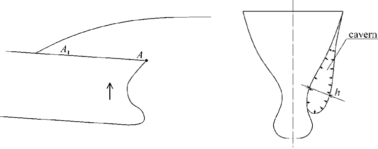
The cause of the damage, according to the authors, is hydrodynamic phenomena that occur when the fore end digs in a wave and subsequent flow around the hull structures as the fore end comes out of the water as a result of the ship's pitching. In this case, at high flow rates around hull structures and the presence of structural cavitators, the pressure in the fore rake drops sharply and cavitation cavities are formed that when slammed onto the hull, create extremely high pressure on the side structures at the fore end of vessels that leads to the destruction of the latter (Fig. 5). When implementing this mechanism, the load acts symmetrically on both sides that corresponds to the nature of the damage received by the vessels.
a b
Fig. 5. Scheme of the formation of a cavitation when flowing around the fore end of a ship:
a – side view of the ship’s hull; b – cross section
Let's consider this phenomenon in more detail. For cavitation to occur, it is necessary that the fore end of the vessel has to be digged in the wave and the edge of the deck (or bulwark) act as a structural cavitator. In this case, the relative velocity of the water flow when flowing around the fore end of the vessel in conditions of its being digged in a wave can be determined from the analysis of pitching of the vessel in conditions of the bow being digged using the calculation methodology presented in [14].
The assessment shows that with a wavelength λ = 150 m and a slope of 1/20 at the fore end, the speed value υ = 9.6 m/s is achieved, and with λ = 300 m and a slope of 1/10 – υ = 27 m/s. These are the relative velocities of the fore end, but with poorly streamlined bodies that are the fore ends when flowing around in the direction from the deck to the bottom, the deck contour (A-A1) will be a structural cavitator where the speed of fluid movement will be significantly higher than the estimate given above. In the future, when conducting research, we will limit ourselves to the speed range from υ = 5 m/s to υ = 30 m/s.
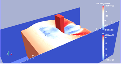
To estimate the degree of pressure drop, a computational experiment was carried out using the DualSPHysics program that implements the SPH method [15-17]. In this case, the fore end of the ship's hull was placed in a fluid flow, the speed of which varied. The pressure was determined at a number of points located in the stem part. The installation diagram for the fore end model is shown in Fig. 6, a.
a b
Fig. 6. Modeling the process of fluid flow around the fore end of the ship’s hull:
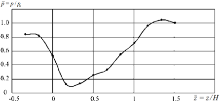
a – model installation diagram; b – change in pressure when a liquid flow flows around the bow end of the vessel
The simulation results are shown in Fig. 6, a that shows the change in pressure ![]() along the height of the stem. The z coordinate is measured from the main plane of the ship in the direction of the deck, i.e.
along the height of the stem. The z coordinate is measured from the main plane of the ship in the direction of the deck, i.e. ![]() corresponds to the deck of a ship. As can be seen from the figure, when a fluid flows around the fore end of a ship’s hull and when it is digged in a wave, zones with a sharp drop in pressure may appear. The figure was constructed for a flow speed of 1.5 m/s, which corresponds to a speed of 15 m/s for nature.
corresponds to the deck of a ship. As can be seen from the figure, when a fluid flows around the fore end of a ship’s hull and when it is digged in a wave, zones with a sharp drop in pressure may appear. The figure was constructed for a flow speed of 1.5 m/s, which corresponds to a speed of 15 m/s for nature.
In the case under consideration, the cavitation number ϰ can be determined from the expression:
![]()
where p is the external pressure at a depth corresponding to the position of a given point of the bow extremity, Pa; psat – pressure of saturated water vapor at a given temperature, Pa; ρ – density of water, kg/m3; υ – the resulting flow velocity around the bow under conditions of its being digged in a wave in a developed oncoming wave, m/s.
An analysis of the experimental results shows that at the above velocity values, the cavitation number turns out to be significantly less than unity that indicates the possibility of cavitation developing in conditions of flow around the fore end of a vessel when it is digged in a wave.
In this case, the process of the formation of large cavities will look like this. The presence of a structural cavitator (A-A1) in the area of the bulwark (or shearstreck in the same area) creates conditions for the occurrence of stall cavitation directly on the structural cavitator. These individual cavities are blown down by a fluid flow (as the fore end of the hull moves upward) into a low-pressure area, where they accumulate, turning into a large cavity, the dimensions of which can reach several meters.
To study this phenomenon, the process of formation of the cavity was simulated when a fluid flows around the fore end using ANSYS FLUENT software. Fig. 7 shows the distribution of the vapor fraction when the fluid flows around the fore end. It can be seen that in the area of the structural cavitator there are areas almost completely occupied by steam (red color), further towards the bottom there are areas in which the steam content is about 50%. Moreover, in real conditions, the nature of the flow of liquid around the fore end will be more complex that is due to the nature of the movement of particles in the wave, the dynamics of the fore end and its transition through the interface between two media (water and air).
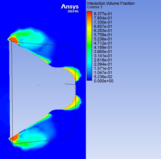
Fig. 7. Distribution of water vapor around the fore end during the formation of a cavitation cavern
It should be noted that cavitation caverns of stall cavitation have a wide variety of shapes – they can be round, parabolic, etc. In this case, caverns of any shape are cavities, the limiting surface of which on the side of the water mass is concave inward [18], forming in the liquid recesses of various shapes, including recesses that correspond in shape to the cumulative one. It has been noted that in a cavitation cavern in its corresponding sections, similar to a cumulative excavation, the formation of high-speed liquid jets is possible according to the laws of cumulation [18].
Since some parts of the surfaces of cavitation caverns are similar to the indicated recesses, the data presented in [18] confirm the possibility of the formation of cumulative jets in cavitation caverns and, thus, make it possible to explain their destructive effect from the point of view of the laws of cumulation [18]. In the same work, the final velocity of the cumulative jet was determined to be 120 m/s. It is noted that during stall cavitation, the cavity diameter decreases only by 2-3 times. With the cumulative formation of jets, the indicated degree of cavity contraction is sufficient to cause destruction [18].
Fig. 2 shows damage to the fore end of the Energy Endurance vessel. It can be seen that the shape of the damage is close to the shape of a circle that clearly indicates destruction caused by a cumulative jet. Fig. 1 and Fig. 3 shows damage to the bow ends of the vessels Atlas Pride and Marcona Trader that have an elongated shape in the form of a rectangle with dimensions of 2.4 × 8.5 m indicating that several cumulative jets were simultaneously exposed, which is unlikely, or cavities collapse occurred without the formation of cumulative jets. The mechanism of cavity collapse without the formation of a cumulative jet is considered, for example, in [19]. It should be noted that the magnitude of the load when the cavitation cavity collapses without the formation of a cumulative jet is also high and can lead to the destruction of ship side structures.
Estimation of the magnitude of hydrodynamic loads during the collapse of a cavitation cavity
To estimate the magnitude of the hydrodynamic pressure acting on the hull structures at the moment of collapse of the cavitation cavern, we consider the dynamics of a certain mass of liquid m per unit area of the hull structure S. To estimate the value of m as a first approximation, we can use the approach outlined in [20] in relation to the assessment impact force of the breaking wave. In this case, the mass of liquid m interacting with the ship's hull on area S can be estimated as the added mass per unit area of the structure. In this case, to determine the added masses in a first approximation, you can use, for example, the method of A. Z. Salkaev [21].
Considering the liquid mass m, when the cavitation cavity collapses, it will move accelerated under the influence of the difference between external and internal pressure. As a first approximation, the pressure of saturated vapors in the cavitation bubble can be neglected; in this case, the dynamics of the fluid element will be described by the equation

where a is the acceleration of the elementary volume of liquid, m/s2; m – mass of the elementary volume of fluid, kg; p – external pressure in the area of the cavitation cavern, Pa; S – area of the hull structure element, m2.
The velocity of the elementary volume of fluid υm at the moment of impact on the outer shell plating will be determined, among other things, by the thickness of the cavitation cavern h and will be determined from the expression
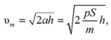
where h is the thickness of the cavitation cavern, m.
To estimate the impact force, you can use the law of conservation of momentum
 (2)
(2)
where ti – impact time, s.
Analysis of experimental data [19] indicates that the time of exposure to a pressure pulse is determined by thousandths of a second.
If the fluid mass m has an initial velocity υm0, expression (2) is transformed to the form
The total value of the hydrodynamic force acting on the structure at the moment of collapse of the cavitation cavern at zero initial speed can be determined from the expression
 where Ω is the area of the cavitation cavern, m2; mΩ – attached mass per unit area of the structure, varying over the area of the cavitation cavity, kg/m2; pΩ – external pressure varying over the area of the cavitation cavern, Pa; hΩ – variable thickness of the cavitation cavern, m.
By varying the values of h, p and ti, it is possible to estimate the pressures acting on the hull when implementing the proposed physical model. Some results are presented in Fig. 8, where ti = 0.001 s, p = 0.1 MPa was taken.
It can be seen that the resulting pressures are at the level of hundreds of tons per square meter, i.e. correspond to the level mentioned in [10]. As the thickness of the cavitation cavity h increases, the level of pressure on the side grillage also increases and can reach several hundred tons per square meter. It can be stated that the proposed physical model explains the reasons for the occurrence of catastrophic destruction in the fore end of ships.
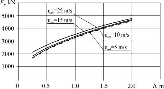
Fig. 8. Results of assessing the magnitude of the loads acting on the fore end
Recommendations for preventing damage to ship structures at the bow end
The occurrence of the destruction described above can be prevented by modernizing the hull structures in the fore end in order to eliminate structural cavitators, the effect of which is manifested when flowing around the deck in the event of the bow end being digged in a wave. For this purpose, the fore end can be equipped with a deck fairing that improves the hydrodynamic characteristics of the structure when flowing in the direction from the deck to the bottom [14]. To improve the operational characteristics of the vessel, this fairing can be made of separate sections with the possibility of their movement [22] depending on sailing conditions.
In addition, it is possible to prevent the occurrence of damage from the collapse of cavitation caverns formed during the flow around the fore end by supplying air to the place where the vacuum occurs in the area of the fore end [23] directly into the cavity cavern.
The implementation of this approach involves the need to equip the vessel with systems for receiving and transporting compressed air to the appropriate areas of the bow. In this case, the supply of compressed air to the outer part of the outer hull should be carried out through valves, the opening of which occurs at a given value of the pressure drop from the outer side of the outer shell of the ship's hull.
When a vessel is equipped with this system, in the event that the fore end is digged in a wave and a fluid flows around it when a zone of low pressure with given parameters occurs in a specific area of the fore end, the valves in this area open and compressed air is supplied, thereby reducing an impact when the cavitation cavern collapses. This allows to prevent damage to hull structures due to high-intensity hydrodynamic loads. The effect of reducing hydrodynamic loads during the collapse of cavitation caverns in the case of gas supply to the cavern is noted, for example, in [24].
Conclusion
Based on the results of the study, the following conclusions can be drawn:
1. In conditions of digging the bow into the wave and the occurrence of cavitation, it is possible to implement the concept of a plane impact of the liquid on the structure, as a result of which the acting loads rush to infinity.
2. The resulting pressure is a weak function of the vertical speed of movement of the fore end of the vessel (see Fig. 8).
3. Destruction of the fore ends due to cavitation can be prevented by implementing measures related to the elimination of structural cavitators in the fore end and improving the conditions of flow around it when digged in a wave, as well as through the use of a special system that supplies air to the place where the vacuum occurs in the area of the bow end.
1. Marine Weather. Ship Handling in Rough Sea, head and countering. P&I Loss prevention bulletin, 2019. Vol. 45. 19 p.
2. Report of FSA Study on Bulk Carrier Safety (MSC75/5/2). IMO Maritime Safety Committee, 2002. 41 p.
3. Departmental Investigation into Certain Aspects Concerning the Loss of the Bulk Carrier Melete in the South Indian Ocean on 24 August 1991 (Report no. 34). Australian transport safety bureau. Canberra, Transport and Communications Publ., 1991. 18 p.
4. Rissige Riesen. Der Spiegel, 1970, no. 25, pp. 105-106.
5. Atlas Pride. Available at: https://www.shipsnostalgia.com/media/atlas-pride.381548/ (accessed: 20.08.2023).
6. The bow of the crude oil tanker Energy Endurance after being struck by a rogue wave. Available at: https://www.reddit.com/r/CatastrophicFailure/comments/wuid26/1981_the_bow_of_the_crude_oil_tanker_energy/?rdt=50211 (accessed: 20.08.2023).
7. Okumoto Y., Takeda Y., Mano M., Okada T. Design of ship hull structures. Berlin, Springer Publ., 2009. 578 p.
8. Liberian Ship Is Reported Sinking in Mid-Pacific, Coast Guard Says. The New York Times, 1981, march 3, section A, p. 7.
9. Ross S. G. So who says its Pacific Ocean. Mariners Weather Log, 1982, vol. 26, no. 4, pp. 196-198.
10. Dotsenko S. F., Ivanov V. A. Volny-ubiitsy [Killer waves]. Sevastopol', Izd-vo Morskogo gidrofizicheskogo instituta NAN Ukrainy, 2006. 43 p.
11. Burakovskii E. P., Burakovskii P. E., Dmitrovskii V. A. Otsenka veroiatnosti vstrechi morskikh sudov s anomal'nymi volnami [Assessment of the probability of meeting ships with abnormal waves]. Morskie intellektual'nye tekhnologii, 2019, no. 4 (46), vol. 4, pp. 10-15.
12. Burakovskii E. P., Burakovskii P. E., Iusyp V. M. Konstruktivnye resheniia, povyshaiushchie bezopasnost' morepla-vaniia v usloviiakh shtorma [Constructive solutions that increase the safety of navigation in storm conditions]. Morskie intel-lektual'nye tekhnologii, 2022, no. 4 (58), vol. 3, pp. 19-26.
13. Jenkins A. D., Magnusson A. K., Niedermeier A., Hagen O., Bitner-Gregersen E., Monbaliu J., Trulsen K. Rogue waves and extreme events in measured time-series. Report WP2/1 from MAXWAVE project. Bergen, Norwegian Meteoro-logical Institute, 2002. 101 p.
14. Burakovskii E. P., Burakovskii P. E., Dmitrovskii V. A. Konstruktivnoe obespechenie bezopasnosti moreplavaniia: monografiia [Constructive safety of navigation: monograph]. Saint Petersburg, Lan' Publ., 2020. 300 p.
15. Crespo A. J. C., Domínguez J. M., Rogers B. D., Gómez-Gesteira M., Longshaw S., Canelas R., Vacondio R., Barreiro A., García-Feal O. DualSPHysics: open-source parallel CFD solver on Smoothed Particle Hydrodynamics (SPH). Computer Physics Communications, 2015, vol. 187, pp. 204-216.
16. Monaghan J. J. Smoothed particle hydrodynamics. Annual Reviews of Astronomy and Astrophysics, 1992, no. 30, pp. 543-574.
17. Burakovskii P. E. Issledovanie vliianiia konstruktivnykh elementov na gidrodinamicheskie sily i momenty, de-istvuiushchie na nosovuiu okonechnost' sudna v usloviiakh ee zaryvaemosti s ispol'zovaniem tekhnologii Smoothed Particle Hydrodynamics (SPH) [Investigation of the influence of structural elements on the hydrodynamic forces and moments acting on the bow tip of the vessel in conditions of its burrowing using the Smoothed Particle Hydrodynamics (SPH) technology]. Morskie intellektual'nye tekhnologii, 2022, no. 4, vol. 3, pp. 39-45.
18. Kozyrev S. P. O kumuliativnom zakhlopyvanii kavitatsionnykh (parovykh) kavern [On the cumulative slamming of cavitation (steam) cavities]. Doklady AN SSSR, 1966, vol. 170, no. 1, pp. 61-63.
19. Albano A., Alexiadis A. Non-symmetrical collapse of an empty cylindrical cavity studied with smoothed particle hy-drodynamics. Applied Sciences, 2021, no. 11, p. 3500.
20. Kholodilin A. N., Shmyrev A. N. Morekhodnost' i stabilizatsiia sudov na volnenii [Seaworthiness and stabi-lization of ships in rough seas]. Leningrad, Sudostroenie Publ., 1976. 328 p.
21. Blagoveshchenskii S. N., Kholodilin A. N. Spravochnik po statike i dinamike korablia: v 2-kh tomakh [Handbook of Ship Statics and Dynamics: in 2 volumes]. Leningrad, Sudostroenie Publ., 1976. Vol. 2. Dinamika (kachka) korablia. 176 p.
22. Burakovskii E. P., Burakovskii P. E. Nosovaia okonechnost' korpusa sudna [The bow tip of the vessel's hull]. Patent RF, no. 2018123395, 04.06.2019.
23. Burakovskii E. P., Burakovskii P. E., Iusyp V. M. Nosovaia okonechnost' korpusa sudna [The bow tip of the vessel's hull]. Patent RF, no. 2022114149, 09.01.2023.
24. Shi Y., Lu J., Gao S., Pan G., Ren J. Experimental study on the cavitation flow and motion characteristics of the vehicle launched underwater. International Journal of Naval Architecture and Ocean Engineering, 2023, no. 15, pp. 1-11.
