


Russian Federation
Sumgait, Azerbaijan
The issue of designing a vision system based on algorithmic and mathematical support is considered. A flexible production system for the manufacture of evaporators of refrigeration units was chosen as the object of research. The analysis of existing projects of technical vision systems (TVS) for quality control of products – evaporators installed on an industrial robot. The purpose and main issues of the implementation of algorithmic and software for the functioning of the TVS and its architecture in accordance with the specifics of the object under study are set. The general scheme of functioning of subsystems of automated design of TVS for quality control of evaporators on a production stream of the flexible production system is offered. A mathematical model has been developed for identifying the evaporator blank, taking into account the corresponding coordinate system, the origin of which is the geometric center of this object, and the X-axis is formed by the largest radius of the image under consideration. The description of the TVS is given taking into account the interaction of the TVS correlator with the graphical terminal. When working with the TVS correlator, the evaporator surface that needs to be recognized is placed in one of the stable states on the working surface of the system, where the orientation coordinates of the evaporator positions are determined. The calculation of the memory volume of the storage system of the correlator TVS is carried out. The issue of forming a working scene for the TVS correlator of an industrial robot by sequentially performing operations to set graphic images of objects in a given array is considered. At the same time, its reflection coefficient (0-100%) is set for each evaporator model.
technical vision system, industrial robot, flexible manufacturing system, product quality control, correlator
Introduction
The process of designing standard elements of control and monitoring of the FPS, the object of study of which is a technical vision system (TVS), due to the flexibility of the controlled program, as well as the machine representation of three-dimensional models of objects, is a complex multi-stage process [1, 2]. At the same time, at the initial stages of design, in order to obtain TVS data in the process of recognizing a defect in a manipulated object (MO) moving on a production line, it is required to create information, mathematical and algorithmic support. The general scheme of functioning of subsystems of computer-aided design of the TVS on the production flow of the flexible production system (FPS) [3] is shown in Fig. 1.
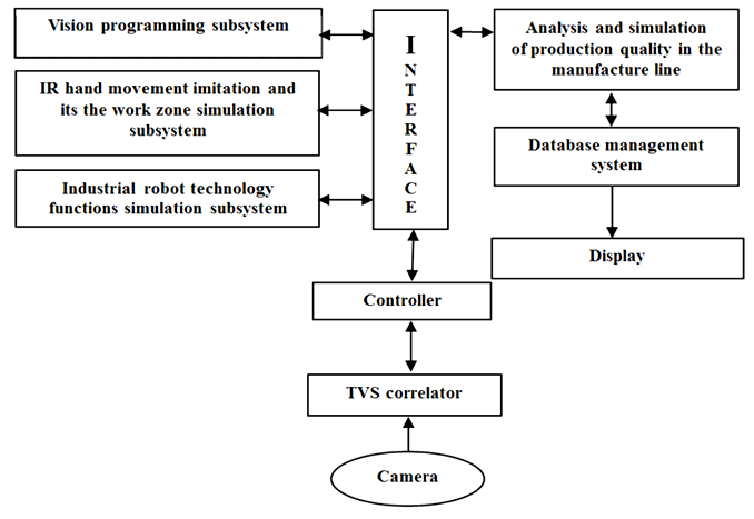
Fig. 1. The general scheme of functioning of subsystems of computer-aided design
of the TVS on the production flow of the FPS
Functional analysis of TVS on the production flow of the FPS
The subsystem for simulating the movement of an industrial robot’s hand and modeling its working area in the general scheme of computer-aided design of the TVS is designed to determine the kinematic parameters of the workpiece in the process of moving its hand from the positioning manipulator of the automated transport system, where it is captured, before it is loaded into the equipment [4].
Structural dimensions (Ai ´ Bi) of the workpiece moving in the space of the working zone of the industrial robot (IR), depending on the type of manufactured product. Based on the assessment of the possibility of achieving PR of individual sections of the working area, spatial coordinates are formed, which are used in a flexible control program for an IR [5].
The study of the production modules of the FPS found that the PR, after capturing the workpiece from the positioning manipulator, moves it along a given ellipsoidal trajectory [6]. In accordance with the trajectory of the movement of the arm of an IR together with the workpiece, its length is determined as follows [6]:

where lt – distance of trajectory; Yinit – initial coordinate at Y axe; Ai, Bi, Ci − respectively, the geometric dimensions of the manipulation object; Zinit – initial coordinate at Z axe; b – the angle of rotation of the IR arm when installing the manipulation object on the technical equipment (TE); Xte – position coordinate of TE at X axis; Zte – position coordinate of TE at Z axis; R – the radius of the rotational movement of the arm IR, performed when it passes from the coordinate system 0YZ to the coordinate system X0Z.
Accordingly, the area of the working zone of the IR is determined as:

where Swz – working area zone; Ztr – transmission at Z coordinate is the movement of the IR hand up and down along the Z axis.
The vision programming module provides simulation of the camera view area, including the generation of characteristics of the actuators, technological equipment are located in the view area and the simulation of various relationships between them.
The subsystem of the database of design automation, which is used by the TVS of IR in the process of work, includes geometric descriptions of objects and profiles of FPS sample objects, previously placed in front of the TVS camera. Based on the information stored in the database, a control program is prepared offline and presented to the controller that controls the movement of the IR. The formation of computing design data of the IR vision system is initiated by issuing queries to the database.
Information (technical characteristics and graphic images) about other active elements can be obtained in a similar way, as a result of a query in the database. The database of the TVS computing design of the IR also contains information about the location and orientation of the camera in relation to the plane of the working plane and the names of the objects of manipulation.
The TVS correlator identifies FPS objects taking into account the corresponding coordinate system, the beginning of which is the geometric center of the object, and the X axis is formed by the largest radius of the image under consideration. The Y-axis is perpendicular to the X-axis and lies in the image plane, and the Z-axis is directed perpendicular to the work surface. In the process of operation, the visual system determines the location of the recognized object by converting the X, Y coordinates of the geometric center of the observed object into the corresponding coordinates on the working surface. This transformation is set as a result of the calibration of the “camera - working surface” system
(Z − coordinate of the object − coincides with Z – coordinate of the working surface). The TVS correlator also performs the necessary transformations to obtain the IR capture points in three-dimensional space, which, in accordance with the coordinates of the IR trajectory, are determined as follows:
– for point T, the coordinates of the gripping device IR;
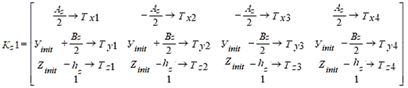
of the IR along its perimeter, along the Y axis (point T); hz – the height of the gripping device (memory) IR; Tz1, Tz2, Tz3, Tz4 are the coordinate points of the ID memory along its perimeter, along the Z axis (point T); – for point С coordinates of gripping device IR:
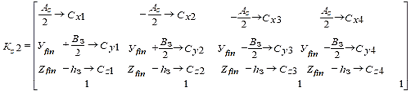
where Kz2 – general coordinates suiting the working zone of IR; Сх1, Сх2, Сх3, Сх4 – coordinate points of the memory of the IR along its perimeter, along the X axis (point C); Yfin – final coordinate at Y axe; Cy1, Cy2, Cy3, Cy4 – coordinate points of the memory of the IR along its perimeter, along the Y axis (point C); Zfin – final coordinate at Y axe; Cz1, Cz2, Cz3, Cz4 are the coordinate points of the IR memory along its perimeter, along the Z axis (point C);
– for point D gripping device coordinates IR:
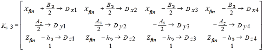
where Kz3 – general coordinates suiting the working zone of IR gripper along coordinates of Dxi; Dx1, Dx2, Dx3, Dx4 – coordinate points of the memory of the IR along its perimeter, along the X axis (point D); Dy1, Dy2, Dy3, Dy4 – coordinate points of the memory of the IR along its perimeter, along the Y axis (point D ); Dz1 , Dz2, Dz3, Dz4 are the coordinate points of the IR memory along its perimeter, along the Z axis (point D);
– for point N, the coordinates of the gripping device IR:
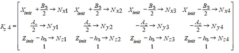
where Kz4 – general coordinates suiting the working zone of IR gripper along coordinates of Nxi; Nх1, Nх2, Nх3, Nх4 – coordinate points of the memory of the IR along its perimeter, along the X axis (point N); Ny1, Ny2, Ny3, Ny4 are the coordinate points of the IR memory along its perimeter, along the Y axis (point N); Nz1, Nz2, Nz3, Nz4 are the coordinate points of the IR memory along its perimeter, along the Z axis (point N).
The interaction of the TVS correlator with the computing design is carried out by selecting from the set (“menu”) specified on the screen of the graphic terminal. When working with the TVS correlator, the objects that need to be recognized are placed in one of the stable states on the working surface of the system. Then he determines the coordinates of the orientation of the MO positions necessary to capture the IR.
When creating TVS correlator, it becomes necessary to develop the hardware and software of the system. In this regard, the radiation source, the receiving optical system, the parameters of the optical radiation receiver and the electronic path for processing the optical information signal (video signal) are selected, the efficiency of the methods for obtaining the transformation and image analysis is evaluated, the methodological and instrumental errors in measuring the parameters of the FPS objects are determined.
One of the main parameters in calculating the TVS correlator is the amount of memory of its storage system, i. e. the amount of information that needs to be remembered. This parameter is defined as [6]:
![]()
where Nk – number of memorized image frames; Ne – number of image decomposition elements; m1 – number of gradations of brightness; m2 – the number of colors in the image.
In the complex, optical information is obtained using real optical information sensors, which are selected according to the permissible parameters: error, which determines the accuracy class of the sensor; measurement limits with guaranteed accuracy; the influence of the physical parameters of the controlled and the environment on the normal operation of the sensor; presence at the installation site of sensors for its normal functioning of vibrations, magnetic and electric fields; the distance over which the information emitted by the sensor can be transmitted; limit values of the measured value and other parameters of the environment.
The formation of a working scene for the correlator of the TVS of IR is performed by sequentially performing operations for setting graphic images of objects in a given array. In this case, for each object model, its reflection coefficient (0-100%) is set [7].
The model of a rectangle, which forms the basis of each working area of the active elements of the flexible production manufacture (FPM) for manufacturing, is written as [8]:
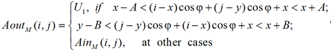
where ![]() – output parameters of the working zone of IR gripper drawing rectangle figure with vectors i and j; U1 – reflection coefficient of the workpiece; x, y are the coordinates of the position of the centers of the rectangle in rows and columns; A – a side of rectangle along X coordinate at drawing trajectory; B – a side of rectangle along X coordinate at drawing trajectory; j – angle of rotation of the rectangle around the center;
– output parameters of the working zone of IR gripper drawing rectangle figure with vectors i and j; U1 – reflection coefficient of the workpiece; x, y are the coordinates of the position of the centers of the rectangle in rows and columns; A – a side of rectangle along X coordinate at drawing trajectory; B – a side of rectangle along X coordinate at drawing trajectory; j – angle of rotation of the rectangle around the center; ![]() – initial parameters of rectangle figure getting at vectors i and j (along coordinates X and Y).
– initial parameters of rectangle figure getting at vectors i and j (along coordinates X and Y).
The transformation and analysis of the image is carried out by the software of the complex, designed to develop and analyze the effectiveness of the algorithmic and software of the TVS correlator. The hardware includes a computer system with a video control device and a simulator of the working area of the elements, blanks with lighting devices. The developed set of technical means is used to receive and input video signals from normalized images into the computer system, which are determined depending on the optical properties of the object and background, the magnitude and direction of their illumination, as well as the parameters of optical radiation and the video signal input unit to the computer [9].
The TVS control unit circuit begins to function when there is a workpiece in the IR fixation zone. After fixing the workpiece, the image sensor transmits video signals to the control computer by means of the video signal input unit, where, after processing information about the state of the objects, the executive commands are transmitted to the IR actuator. To increase the level of illumination of the smooth and oval surface of the workpiece, the image sensor of the TVS is supported by lighting means.
The camera is installed above the IR of the automatic conveyor at the input of the production module of the FPS. When the workpiece appears in the field of view of the camera (when the workpiece is fixed on the actuators), it detects defects by observing its surface.
If there are defects on the surface of the workpiece, the video information is sent for recognition to the information processing preprocessor system, and then to the video processor, where the latter acts on the IR control system, which captures and moves this product. Upon receipt of video information about the presence
of a defect on the workpiece, the gripper IR after its capture, sequentially moves straight up along the Z axis (Dz), rotates around the coordinate Z axis by an angle
of j1 and moving down along the Z axis (2 Dz), sets the workpiece on the table for defective products. Further along the same trajectory, the PR arm returns to its original position. In the absence of a defect in the workpiece, after its capture, the IR hand will move the finished MO to the position of the nearby IR.
The process of obtaining information from video sensors is associated with the coordinate systems of the product and the camera. The kinematical connection of the workpiece and camera coordinate systems is represented as:
![]() (1)
(1)
where Mk–1 – the inverse transformation matrix, Mk – which describes the position of the camera coordinate system relative to the IR gripper; Mdz − matrix of the relative position of the IR gripper during its rectilinear downward movement. On Fig. 2 shows a block diagram of the developed TVS of IR, which operates in the production module of the FPS sections.
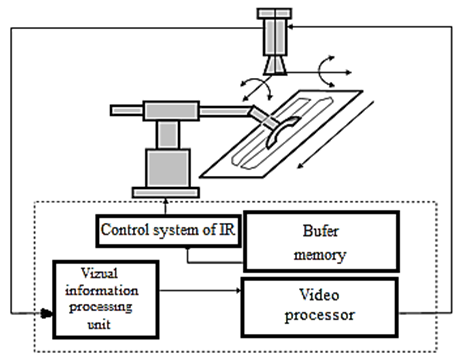
Fig. 2. Block diagram of TVS of IR for visual control of a tool in the production line
As seen from Fig. 2, the block diagram consists of an information processing processor, a video processor, a buffer memory that is part of the computer, IR control system and a television camera installed on the production line. The computer output is connected to the IR control system.
The camera that monitors the movement of the MO, in the presence of a product on the IR, to recognize defects along the perimeter of a flat product, sequentially rotates around the Y and X coordinate axes.
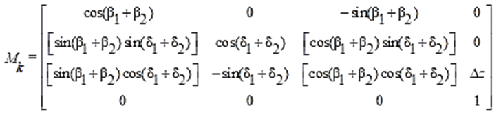
Transformation matrices Mk, describing the position of the camera coordinate system relative to the IR memory are written as follows:
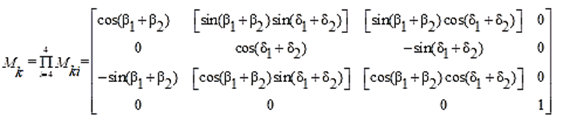 (2)
(2)
where Mki – inverse matrices getting on i positions trajectory of IR; b1 and b2, d1 and d2 − respectively, the angles of rotation around the coordinate axis Y, X .
Taking into account (1), (2) and the coordinates
of the relative position of the IR memory, where can obtain the matrix of the kinematic connection of the coordinate systems of the MO and the camera in the view:
 .
.
Conclusion
The developed kinematic model of the TVS device functioning, which forms the basis of the mathematical software for the automated design of the TVS, makes it possible to increase the efficiency and reliability of the operation of the PR control system and the production module of the FPS.
1. Larkin E. V., Budkov S. A. Opredelenie pros-transtvennogo polozheniia rabochego organa [Determination of the spatial position of the working body]. Izvestiia Tul'skogo gosudarstvennogo universiteta. Tekhnicheskie nauki, 2013, iss. 10, pp. 197-203.
2. Larkin E. V., Kotov V. V., Kotova N. A. Sistema tekhnicheskogo zreniia robota s panoramnym obzorom [The robot's technical vision system with a panoramic view]. Izvestiia Tul'skogo gosudarstvennogo universiteta. Tekhnicheskie nauki, 2009, iss. 2, part 2, pp. 161-166.
3. Androsov A. Iu., Gorshkov A. A., Lutskov Iu. I. Razmeshchenie sistemy tekhnicheskogo zreniia na manipuliatore mobil'nogo robota [Placement of the vision system on the manipulator of a mobile robot]. Izvestiia Tul'skogo gosudarstvennogo universiteta. Tekhnicheskie nauki, 2014, iss. 11, part 1, pp. 418-426.
4. Mammadov J. F., Salmanov M. S., Aliyeva A. G. Providing intelligence functions of control system of technological process. Novye zadachi tekhnicheskikh nauk i puti ikh resheniia: sbornik trudov Mezhdunarodnoi nauchno-prakticheskoi konferentsii (Ufa, 01 sentiabria 2014 g.). Ufa, Aeterna Publ., 2014. Pp. 32-34.
5. Klevalin V. A., Polivanov A. Iu. Tsifrovye metody raspoznavaniia v sistemakh tekhnicheskogo zreniia promyshlennykh robotov [Digital recognition methods in industrial robot vision systems]. Mekhatronika, avtomati-zatsiia, upravlenie, 2008, no. 5, pp. 56-56.
6. Fedotkin I. M. Matematicheskoe modelirovanie tekhnologicheskikh protsessov [Mathematical modeling of technological processes]. Moscow, Librokom Publ., 2011. 416 p.
7. Semin M. S. Prikladnye zadachi, reshaemye s pomoshch'iu sistem tekhnicheskogo zreniia [Applied tasks solved with the help of vision systems]. Spetsial'naia tekhnika, 2002, no. 6, pp. 12-17.
8. Mamedov Dzh. F., Abdullaev G. S., Mamedova Sh. T., Valieva B. A., Popova O. I. Avtomatizirovannyi vybor i proektirovanie elementov sistemy upravleniia gibkogo avtomatizirovannogo proizvodstva [Automated selection and design of control system elements for flexible automated production]. Vestnik Voronezhskogo gosudarstvennogo tekhnicheskogo universiteta, 2019, vol. 15, no. 1, pp. 107-111.
9. Mamedov Dzh. F., Abdullaev G. S., Valieva B. A., Mamedova Sh. T., Genzhelieva G. G. Issledovanie iz-meritel'noi-upravliaiushchei sistemy na baze gibkogo pro-izvodstvennogo uchastka [Investigation of the measuring and control system based on a flexible production site]. Informatsionnye tekhnologii intellektual'noi podderzhki priniatiia reshenii (ITIDS'2018): sbornik trudov VI Vserossiiskoi konferentsii (Ufa - Stavropol', 28-31 maia 2018 g.). Ufa, Izd-vo Ufim. gos. aviats. tekhn. un-ta, 2018. Vol. 1. Pp. 27-30.
