


Kerch, Simferopol, Russian Federation
The article considers the problems of the Russian fishing fleet. The trawlers whose age exceeds thirty years are actively operating along with commissioning of the new fishing vessels. Over such a long service life, they lose the necessary traction force due to the increased resistance of the hull and wear of the propulsion system. The possibility of rapid assessment of the traction characteristics of the vessel has been illustrated on the example of a large trawler-freezer type “Pulkovo meridian” project 1288, which has been in use since 1982. The dependence of the ship loss of traction on the voyage time was derived as well. Moreover, there is proposed a method for reducing the hydrodynamic resistance of the trawl system by replacing nylon mesh panels of a trawl’s net part with mesh panels of a smaller tie diameter made of modern high-strength materials. In preparation for the fishing voyage, it is necessary to store up consumables for trawl repairing, so if the fishing vessel-trawl is properly operated, such net sheets should be included in the consolidated list of materials. Numerical examples of the method are given here as well. As a result of applying this method, substituting the panels of the net part with a mesh pitch of 1 200 and 800 mm of the pelagic trawl P-K-120/1120 for the mesh panels made of high-strength Dyneema material can reduce the hydrodynamic resistance of the trawl by 1.3 times. The proposed methodology for determining a trawler’s commercial viability and correcting the hydrodynamically heavy fishing gear should solve the problem of the optimal correlation between the propulsion of a vessel and the hydrodynamic resistance of a trawl quickly, in the process of fishing by a crew of a vessel. The proposed methodologies would help avoid high main engine maintenance costs, operating a trawl that is not in line with the technical condition of the trawler or reduce fishing shortfalls of a smaller trawl.
trawl, actual traction, trawler, trawl resistance, fishing suitability, filament diameter, rope diameter
Introduction
The fisheries industry of the Russian Federation, focusing on the indicators of the Food Security Doctrine of the Russian Federation, should provide an internal consumption market of fish products by at least 85%. Such a level should be provided in all areas of work of the fisheries industry.
“The main purpose of the operation of the fishery complex is to meet the needs for fish products for food and non-food purposes. It is the primary sector of the fishery complex – fishing and fish farming, in many ways determines the structure, scale and specific functions of the elements of the national economy, in general, and the fishery complex, in particular” [1, p. 564]. The Russian Federation is still one of the five world leaders in fisheries. Russian fishermen produce about 5 million tons of aquatic bioresources despite the fact that the number of fishing vessels decreased by 75% compared to 1995, and the average age of mining vessels is 30.9 years old. To this date, a state program for the renewal of the fishing fleet has been developed and is being implemented. According to this program it is planned to build 43 trawlers and longline vessels and about 40 crab boats by the end of 2025. However, previously defined construction dates will be shifted because of the sanctions policy and it is difficult to supply the navigational and fishing search equipment needed to equip the fishing vessel. In addition to newly commissioned mining vessels, many fishing companies actively use vessels built in the USSR. There are about eleven large trawler-freezers of “Pulkovo meridian” project 1288, years of construction of which from 1981 to 1990, that operate in the Oceanrybflot, JSC. Taking into account the deadline shifting in the renewal of the fishing fleet, it is necessary to competently and safely exploit the existing companies mining fleet. On the basis of previously collected statistical materials and the proposed methods it is considered possible to manage the compatibility of components of the system “vessel-trawl” in a fishing voyage on the example of a large trawler-freezer type “Pulkovo meridian” project 1288.
Research materials
The ability of a fishing vessel to tow a trawl is determined by its pull. The work [2] concluded that the traction characteristics of a trawler depend not only on the capabilities of the vessel itself – the power developed by the engine, “…the speed of trawling, but also from external factors – the operating conditions of the vessel, such as the navigation area, relation of running and parking time, the time from the last docking, the duration of the fishing voyage and the total service life of the vessel” [2, p. 104]. In order to assess what traction capabilities, the vessel has at the moment, it is necessary to have a notion of “reference” thrust, that is, to know what traction the new vessel had at a certain engine and speed of trawling.
The test reports of vessels with construction numbers 1 and 11 [3, 4] were used to obtain the traction dependence of the new vessel project 1288 (Table 1: where Ne – the power transferred to the propeller, kW; V – vessel speed, knots; Pp – force of thrust, kN).
Table 1
Data about tests of LFT type “Pulkovo meridian” project 1288
|
Test no. |
Ne, kW |
V, knots |
Рp, kN |
|
Ne, kW |
V, knots |
Рp, kN |
Test |
Ne, kW |
V, knots |
Рp, kN |
|
1 |
3 500 |
0 |
464 |
15 |
2 200 |
13.0 |
0 |
29 |
3 000 |
12.0 |
93 |
|
2 |
3 200 |
0 |
435 |
16 |
2 000 |
12.5 |
0 |
30 |
3 000 |
14.0 |
20 |
|
3 |
3 000 |
0 |
412 |
17 |
3 500 |
2.0 |
428 |
31 |
2 000 |
2.0 |
251 |
|
4 |
2 800 |
0 |
389 |
18 |
3 500 |
4.0 |
377 |
32 |
2 000 |
4.0 |
216 |
|
5 |
2 600 |
0 |
368 |
19 |
3 500 |
6.0 |
314 |
33 |
2 000 |
6.0 |
172 |
|
6 |
2 400 |
0 |
336 |
20 |
3 500 |
8.0 |
273 |
34 |
2 000 |
8.0 |
128 |
|
7 |
2 200 |
0 |
311 |
21 |
3 500 |
10.0 |
191 |
35 |
2 000 |
10.0 |
78 |
|
8 |
2 000 |
0 |
282 |
22 |
3 500 |
12.0 |
129 |
36 |
2 000 |
12.0 |
20 |
|
9 |
3 500 |
15.2 |
0 |
23 |
3 500 |
14.0 |
59 |
37 |
580 |
0 |
0 |
|
10 |
3 200 |
14.7 |
0 |
24 |
3 000 |
2.0 |
373 |
38 |
3 800 |
6.0 |
350 |
|
11 |
3 000 |
14.5 |
0 |
25 |
3 000 |
4.0 |
321 |
39 |
4 000 |
16.2 |
0 |
|
12 |
2 800 |
14.1 |
0 |
26 |
3 000 |
6.0 |
267 |
40 |
2 300 |
12.8 |
0 |
|
13 |
2 600 |
13.7 |
0 |
27 |
3 000 |
8.0 |
211 |
41 |
1 200 |
6.0 |
0 |
|
14 |
2 400 |
13.3 |
0 |
28 |
3 000 |
10.0 |
157 |
– |
– |
– |
– |
|
|
According to the data given in Table 1, we have obtained equation by which it is possible to determine the force of thrust which fishing vessels of project
1288 were able to provide at the beginning of operation:
The coefficients of dependence (1) were obtained in [2], by statistical processing of the data given in Table 1. Dependency (1) reproduces Table 1 data to σ (Pp) = 18 kN, which can be considered satisfactory.
A chart of traction of vessels project 1288, at different power transferred to the main engine propeller Ne = 1 000, 1 500, 2 000, 2 500, 3 000, 3 500, 4 000 kW, is shown in Fig. 1.
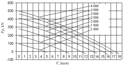
Fig. 1. Traction of the new large trawler-freezer project 1288
The obtained trawler thrust equation, depending on the engine power and speed, will allow to determine the actual thrust of the vessel, taking from the obtained value the total loss of thrust, the detailed method of determination of which is described in [2].
In [5] there are ship tests materials of the project 1288 “Pulkovo meridian” LFT “Marshall Vasilevsky”, which is still in operation. Some test results are summarized in Table 2 (where Vv – vessel speed, knots; Nsg – the capacity taken by the shaft generator, kW; q – wind course, deg.; Vw – wind speed, knots; tg – exhaust gas temperature, °C; Pb – boost pressure, kg/cm2).
Table 2
Test data of LFT “Marshal Vasilevsky”
|
Test no. |
Timing from the beginning |
Step, deg. |
Vv, knots |
Nsg, kW |
Wind |
Indirect characteristics |
||||
|
q, deg. |
Vw, knots |
ME 1 |
ME 2 |
|||||||
|
tg, °C |
|
tg, °C |
|
|||||||
|
1 |
12 |
7.5 |
13.7 |
600 |
0 |
10.0 |
414 |
1.33 |
404 |
0.68 |
|
2 |
22 |
8.0 |
16.1 |
510 |
170 |
14.0 |
419 |
1.28 |
419 |
0.95 |
|
3 |
23 |
7.8 |
15.3 |
500 |
170 |
9.5 |
423 |
1.23 |
425 |
0.80 |
|
4 |
38 |
7.7 |
14.3 |
620 |
8 |
6.0 |
439 |
1.25 |
415 |
0.50 |
|
5 |
39 |
7.8 |
14.3 |
600 |
7 |
5.7 |
436 |
1.25 |
425 |
0.62 |
|
6 |
59 |
7.0 |
12.9 |
650 |
0 |
6.8 |
428 |
1.20 |
410 |
0.49 |
|
7 |
70 |
8.0 |
11.4 |
1 300 |
0 |
8.0 |
432 |
1.27 |
428 |
0.74 |
|
8 |
80 |
7.3 |
13.5 |
450 |
168 |
7.6 |
433 |
1.25 |
420 |
0.48 |

The sequence of processing of the statistical material presented in Table 2 is following:
– by the dependence
the speed of the essel without wind was calculated, where
Using the statistical material given in the in the Table 6.1 in [5], we received a dependency:
to determine the speed of the vessel without taking into account the wind, which can be recommended for use for vessels such as “Pulkovo meridian”;
– the power transferred to the propeller of the vessel was determined by the dependencies received for vessels of project 1288 in [2]:
where “
– the value of the traction loss ΔPp was calculated using the methodology developed in [2].
Table 2 processing results are summarized in Table 3 (where ΔPfr – loss of propulsion of the vessel in free run (without trawl), kN.
Table 3
Materials processing
|
No. of regime |
Neme, kW |
Ne, kW |
VС , knots |
ΔPfr , kN |
|
1 |
4 207 |
3 575 |
14.65 |
67.5 |
|
2 |
4 499 |
3 962 |
14.27 |
108.6 |
|
3 |
4 468 |
3 942 |
14.36 |
104.1 |
|
4 |
4 357 |
3 705 |
14.64 |
77.8 |
|
5 |
4 484 |
3 853 |
14.64 |
88.2 |
|
6 |
4 190 |
3 506 |
13.36 |
108.1 |
|
7 |
4 556 |
3 188 |
12.00 |
125.4 |
|
8 |
4 338 |
3 864 |
12.90 |
150.8 |
As a result of Table 3 processing, there was a dependence of the loss of traction by the vessel on free running on the time of the voyage, in the form
of
Correlation coefficient r = 0.79; standard deviation σ = ±15.3 kN, relative error ε = ±14.7%.
According to the trawl conditions:
The equation of loss of thrust – on the twenty-second day of the voyage:
ΔРp22 = 33.7 + 3.66Vt ; ΔРp22 = 53.83 kN;
Ppa22 = Pp – ΔPp22 = 354.14 – 53.83 = 300.3 kN,
where Ppa22 – actual thrust of the vessel for twenty-second day of the voyage, kN;
– for the seventieth day:
ΔРp70 = 75.4 + 4.3Vt ; ΔРp70 = 99.05 kN;
Ppa70 = Pp – ΔPp70 = 354.14 – 99.05 = 255.09 kN,
where Ppa70 – actual thrust of the vessel for seventieth day of the voyage, kN.
Taking Plim = 180 kN, as the minimum thrust limit, when the vessel has to be repaired, we will calculate the change in the vessel’s fishing suitability by thrust (VFST) for 48 days of voyage as follows:
on the 22nd day
on the 70th day
The ship’s traction capacity will drop to 69.08 – 43.12 = 25.96%, which means that the trawler’s traction capacity will decrease by 0.54% per day.
In conditions of lack of traction of the ship, trawls on board of the ship may become hydrodynamically heavy, in this case it is possible, and sometimes necessary, to make changes to the construction of the trawl in order to, that its resistance corresponds to the thrust of the vessel in order to maintain the speed of the trawl and to avoid excessive loads on the vessel’s engine. Previously, the work [6] described methods of modernization of the trawl by changing the fictitious area of the net part of the trawl and replacing some panels of the wound part of the trawl with a larger mesh pitch. The upgrade opportunities are not running out.
The implementation of state-of-the-art high-strength materials into fishery will significantly reduce the diameter of the ropes from which the mesh is made, and thus reduce the resistance of the trawl.
When calculating the hydrodynamic resistance of a trawl, all the hydrodynamic drag elements of the trawl system are summed:
where Rtr – the resistance force of the trawl system, kN; Rw – wire resistance force, kN; Rb – resistance force of trawl boards, kN; Rcr – cable rigging resistance force, kN; Rload – the trawl loading resistance force, kN; Rfloat – the resistance force of large float and hydrodynamic shield, kN; Rr.p – rope part resistance force of the trawl, kN; Rn.p – the resistance force of the net part of the trawl, kN.
It was previously noted [6] that in the conditions of the fishing deck it is difficult to change the rope part of the trawl, the resistance force of which contributes significantly to the general resistance of the trawl system, it is more convenient to make changes to the net part, the resistance force of which is not less than the rope part of the trawl.
When calculating the resistance force of the net part is used as the resistance square – the thread square of the mesh part of the trawl, which is calculated by dependence:
where Ffi – fictional square of the net part of the trawl, m2; Fr – relative square of the net part of the trawl, n – number of the net part of the trawl
where dw.a – weighted average value of diameter of threads/ropes of the net part of the trawl, mm; аw.a – weighted average of the mesh pitch, mm; Ux, Uy – horizontal and vertical seating´s coefficients.
It is obvious that the resistance force of the net part is directly proportional depends on the diameter of the threads/ropes of the layers, the smaller the diameter of the sections, the less hydrodynamic resistance will be. Consider the effect on the resistance force of nylon panels replacement on panels made of high-strength material with a smaller diameter and higher strength than the nylon, widely used in trawl construction. In commercial fisheries, the Dyneema, high-strength material, has been exploited for over 15 years and has
a strength of 3.6 times higher than that of the nylon. From the theory of similarity, it is known that:
where Сd – scale of diameters of threads, ropes, wires; СR – force scale; Сn – scale of safety margin; Сσ – the voltage limit scale.
If the operating conditions of the trawl are not changed (the same type of vessel, the same fishing area), then Сn = 1. Then
On the other hand, from the theory of similarity we have: if we do not change the speed of trawling (Сv = 1), linear dimensions of the trawl (СL = 1), then
CR = CF ,
where СF – the scale of the square resistance. But:
where CL – linear scale; Ca – scale of the mesh size.
If you don’t change the mesh pitch (Са = 1), so СR = CF = Сd.
Since the trawl consists of parts with different tie diameters, the diameter of the trawl materials must be said as a weighted average:
where di – the coupling diameter of the i-th part, mm; Fi – net square of the i-th panel, m2.
To illustrate the theory of the question, consider a numerical example, for this purpose trawl 120/1120, used on the project 1288 vessels. Table 4 shows the thread square of the mesh part of the trawl (where a – mesh pitch, mm; d – diameter of rope/thread mesh, mm; n1 – amount of mesh of the plate top edge; n2 – amount of mesh of the plate lower edge; m – amount of mesh by plate height; l01 – length in the harness of the top edge of the plate, m; l02 – length in the harness of the lower edge of the plate, m; h0 – height in the plate harness, m; Ff – fictional square of the net part of the trawl, m2; Ft – thread square of the mesh part of the trawl, m2).
Table 4
Thread square of trawl 120/1120
|
No. |
a, mm |
d, mm |
n1, mm |
n2, mm |
m, m |
l01, m |
l02, m |
h0, m |
Ff, m2 |
Ft, m2 |
|
1 |
1 200 |
6.0 |
22 |
19 |
11.5 |
52.8 |
45.6 |
27.6 |
10 863 |
54.32 |
|
2 |
800 |
6.0 |
24 |
19 |
10.5 |
38.4 |
30.4 |
16.8 |
4 623 |
34.68 |
|
3 |
400 |
4.0 |
36 |
32 |
10.0 |
28.8 |
25.6 |
8.0 |
1 741 |
17.41 |
|
4 |
200 |
3.1 |
50 |
45 |
12.5 |
20.0 |
18.0 |
5.0 |
760 |
11.78 |
|
5 |
100 |
2.4 |
84 |
69 |
53.5 |
16.8 |
13.8 |
10.7 |
1 310 |
31.43 |
|
6 |
65 |
2.4 |
92 |
61 |
107.5 |
11.96 |
7.93 |
13.975 |
1 112 |
41.05 |
|
Σ Ft |
190.6 |
|||||||||
With its help and by dependence (3) determine the weighted average value of diameter of the threads/ropes
of the nature trawl dw.a. N:
In the work [6] it was calculated that the linear scale of СL2 = CR, inversely СL2 = CFtr, therefore CFtr = CR, and given the dependence of the conditions, that the trawl 120/1120 has an area equal: FRP = 135.7 m2; FNP = 190.2 m2; Ftr = 326 m2, (where FRP – square of the rope part of the trawl, m2; FNP – square of the net part of the trawl, m2; Ftr – total square of the trawl, m2), the scale coefficient value of similarity of the square of the net part of the trawl model is received CFNM = CR = 0.7354.
It was noted above that if the mesh pitch in the net part of the trawl is not changed, Сd = СR then the average weighted diameter of the upgraded trawl should be equal to
FRP=135,7m2; FNP =190,2 m2; Ftr= 326 m2, .
When replacing a nylon panel with a Dyneema panel, the dependency diameter scale (2) must be used if the strength is equal:
Consider the case of replacing the plate of the bag, which is made with the mesh pitch of 1 200 out of rope diameter 6 mm:
Since the diameter is less than 3 mm, it is no longer a rope, but a thread, the parameters of which should be determined. From [7] it is known that the Dyneema material is produced from yarn 200 tex, determine the number of folds of this yarn:
where n – the number of fold yarn; d – diameter of the thread, mm; K – coefficient (K = 1,6); T – tex the yarn:
There can be no such number of folds. Choose from a series of fold numbers near the calculated value: n = ..., 12, 15, 18, 24. The nearest number is towards increasing strength n = 15. Then the diameter of the thread will be final:
Replace the nylon panel with a mesh pitch 1 200 mm on a Dyneema mesh pitch plate made of 2.8 mm thread diameter. Then the average weighted diameter of the bag will be:
The calculated value of dw.a.M is bigger than the determined one by the similarity condition dw.a.M = 3.0485 mm. Therefore, it is necessary to change the material of the panel with a mesh pitch 800 mm. Then the calculated value of the weighted average diameter will be:
The resulting value is 5 percent lower than required, which is acceptable in technical calculations. In this way, we will replace the 1 200 mm mesh pitch in the rotary part of the trawl and the 800 mm mesh pitch, 6 mm in diameter of nylon threads, with high-strength material, with the same mesh pitch but with a smaller tie diameter, in particular, as in this example, the Dyneema material, 2.8 mm in diameter.
Then the thread square for the first plate will be:
Conclusion
Wear and tear during the entire life of the vessel is unavoidable, and there is also a decrease in the traction characteristics of the trawler during the fishing voyage, which may affect the performance of the vessel, especially when it is in service for decades. The developed methodology of the traction value determination of a vessel in a new state and traction loss determination will allow to identify the actual trawler thrust at the present time. The implementation of the concept of fishing suitability of the vessel makes it possible to assess the fishing potential of the trawler and, when critical values are reached, to take measures to reduce the vessel load. One of such measures is the modernization of the net part of the trawler by replacing the nylon panels with panels made of material with a smaller tie diameter and bigger strength, such as Dyneema, or other modern durable material, which should be taken on the voyage as spare consumables. Of course, the price of such net fabric is much higher than the traditional nylon, but the cost of acquiring them will be covered by the vessel’s trouble-free fishing activities.
1. Yarkina N. N., Ushakov V. V. Rybohozyaystvennyy kompleks Rossiyskoy Federacii: sektoral'no-funkcional'naya sistematizaciya i strukturirovanie v kontekste ustoychivogo razvitiya // Vestn. Kerch. gos. mor. tehnolog. un-ta. 2022. № 4. S. 561-575.
2. Ryazanova T. V. Povyshenie effektivnosti promyslovoy ekspluatacii traulerov na osnove faktornogo analiza ih tyag: dis. … kand. tehn. nauk. Kaliningrad, 2011. 168 s.
3. Otchet po kompleksnym ekspluatacionnym ispy-taniyam bol'shogo morozil'nogo traulera-rybzavoda «Bazhenovsk». Proekt 1288. Proektant CKB «Vostok» Stroitel'nyy № 511. Nikolaev: Chernomorskiy SSZ, 1980. 96 s.
4. Priemnyy akt golovnogo bol'shogo morozil'nogo traulera-rybozavoda «Pulkovskiy meridian» stroitel'nyy № 501. Proekt 1288. Proektant CKB «Vostok». Nikolaev: Chernomorskiy SSZ, 1974. 138 s.
5. Issledovanie vzaimodeystviya sistemy sudovaya silovaya ustanovka - tralovaya lebedka-tral s cel'yu sovershenstvovaniya ee rezhimov ekspluatacii: otchet o NIR. № gos. registracii 01.8300448779. Kaliningrad: Izd-vo KTIRPH, 1985. 135 s.
6. Ryazanova T. V. Metody modernizacii rybolovnogo trala v usloviyah deficita tyagi sudna v techenie promyslovogo reysa // Vestn. Astrahan. gos. tehn. un-ta. Ser.: Morskaya tehnika i tehnologiya. 2021. № 3. S. 52-59.
7. Net Sistems. Katalog produkcii. Bainbridge Is-land, Washington: Minden Editorial Servises, Inc., 2006. 164 p.
